Reinforced Concrete Beam Detailing According to ACI Code
Clearly, the detailing of the reinforced concrete members is the key to good design and execution of work at the site.That is why poor detailing of reinforcement makes the structure undergo cracking, excessive deflection, or even collapse.
Reinforcements resist tensile forces. They may also be required in the compression zones to increase the compression capacity, enhance ductility, to reduce long-term deflections, or increase the flexural capacity for beams.
Added to that, they prevent cracking of concrete due to shrinkage and temperature stresses.
Finally, different aspects of reinforced concrete beam detailing based on ACI Code is explained in the following sections.
Types of reinforcement in a beam
- Main bars (bottom steels)- deal with tension force
- Top bars (anchor bars)-hold stirrups in their position
- Cut off bars- deal with tension forces
- Stirrups with different spacing-tackle vertical and diagonal shear.
Hooked anchors
The function of hooked anchors is the provision of additional anchorage when there is inadequate straight length available to develop a bar.
Commonly, standard hooks described in ACI Code Section 7.1 utilized apart from the case where it is specifically specified.
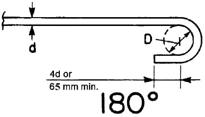
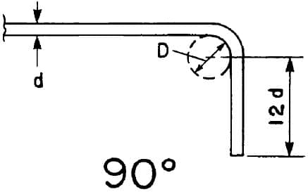
The ACI standard hooks are as follows:
ACI standard hooks for primary reinforcement
- 180-degree bend plus 4db extension, but not less than 65 mm at free end of bar.
- 90-degree bend plus 12db extension at free end of bar.
ACI standard hooks for stirrups
- 16 bar and smaller, 90-degree bend plus 6db extension at free end of bar.
- 19, No. 22, and No. 25 bar, 90-degree bend plus 12db extension at free end of bar
- 25 bar and smaller, 135-degree bend plus 6db extension at free end of bar.
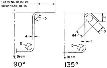
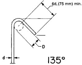
Minimum bend diameters
Standard bends in reinforcing bars are described in terms of the inside diameter of bend because this is easier to measure than the radius of bend.
The primary factors which control the minimum bend diameter are feasibility of bending without breakage and avoidance of crushing the concrete inside the bend.
- Diameter of bend measured on the inside of the bar, other than for stirrups in sizes No. 10 through No. 16, shall not be less than the values in Table 1.
- Inside diameter of bend for stirrups shall not be less than 4db for No. 16 bar and smaller. For bars larger than No. 16, diameter of bend shall be in accordance with Table 1.
- Inside diameter of bend in welded wire reinforcement for stirrups shall not be less than 4db for deformed wire larger than MD40 and 2db for all other wires. Bends with inside diameter of less than 8db shall not be less than 4db from nearest welded intersection.
Table 1 minimum inside diameter of hooks based on the size of the bars
| Bar size | Minimum diameter |
| No.10 to No.25 | 6db |
| No.29, No.32, and No.36 | 8db |
| No.43 and No.57 | 10db |
| db is the diameter of the bar | |

Stirrups
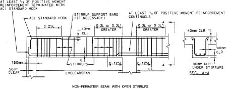
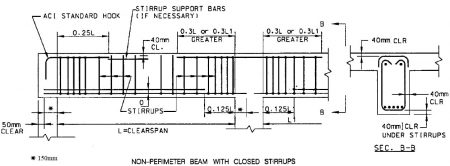
In beam detailing, the detailer or designer shall provide sizes, spacing, location, and types of all stirrups which include open and closed stirrups. stirrups may be vertical or inclined.
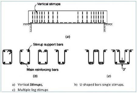
Moreover, where the design requires closed stirrup for shear, the closure may consist of overlapped, standard 90o end hooks of one or two-piece stirrups, or properly spliced pairs of U-stirrups.
Furthermore, when the design requires closed ties for torsion, the closure may consist of overlapped, standard 135o hooks of one- or two-piece ties enclosing a longitudinal bar.
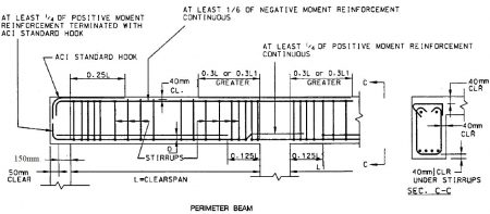
Lastly, there are different techniques for anchorage of stirrups, but the most common is to use one of the standard hooks as shown in figure 3 and figure 4.
Development length (ld)
The development length (ld) is the shortest length of bar in which the bar stress can increase from zero to the yield strength (fy). It is different in tension and compression, and basic equation for each case are as follow:
Development length in tension
Use the following expression to calculate development length in tension, but no less than 30.48cm.

Where:
cb: factor that represents the smallest of the side cover. the cover over the bar or wire (in both cases measured to the center of the bar or wire)
Ktr: factor which denotes the contribution of confining reinforcement across potential splitting planes.
(cb+ Ktr)/db equal to 2.5 if the result of (cb + Ktr)/db is less than 2.5.
db: bar diameter
Atr: total cross-sectional area of all transverse reinforcement within the spacing s.
n: number of bars or wires being developed along the plane of splitting
| Factor in development length equation | Cases | Values |
| Horizontal reinforcement so placed that more than 30cm of fresh concrete cast in the member below the development length or splice | 1.3 | |
| Other reinforcement | 1 | |
| Epoxy-coated bars or wires with cover less than 3db or clear spacing less than 6db | 1.5 | |
| All other epoxy-coated bars or wires | 1.2 | |
| Uncoated and galvanized reinforcement | 1 | |
| No. 19 and smaller bars and deformed wires | 0.8 | |
| No. 22 and larger bars | 1 | |
| For lightweight-aggregate concrete utilization | 0.75 | |
| when the splitting tensile strength is specified, it is equal to fc’^0.5/1.8fct but not more | 1 | |
| for normal-weight concrete | 1 |
Development length in compression
development length can be calculated using the greatest of the following formula, but it shall not be smaller than 20.32cm.
ldc=(0.02fy / )db Equation 3
ldc=( (0.0003fy)db Equation 4
where
ldc: development length in compression bars
fy: yield strength of bars
db: bar diameter
Development of bundled bars
Individual bar development length within a bundle, in tension or compression, shall be that for the individual bar, increased 20 percent for three-bar bundle, and 33 percent for four-bar bundle.
Development Length ldh for standard hooks in tension
The development length, ldh, for standard hooks in tension is given as:

Where:
For other cases,  and
and  are equal to 1.0.

Bar cut off in beams and development length in flexural reinforcement
Bar cut off in beams
Commonly, reinforcements are provided close to the bottom of beams so as to counter act tensile forces on the beam.
Moreover, these reinforcements computed based on maximum moments at mid spans and at face of supports. these moments reduce in beam regions other than mid span and support faces.
Therefore, it is possible to cut off bars in zones where they are no longer required. hence, cut off bars provide economic advantages.
However, bar cut off shall be kept as minimum as possible to decline design and construction complexities.
Furthermore, it is important to extend the cut off bars beyond cut off point by development length (ld) to ensure adequate bond between bar and concrete. Development length will be discussed in the section below.
Lastly, the location of points where bars are no longer needed is a function of the flexural tensions that results from the bending moments and the effects of shear on these tensile forces.
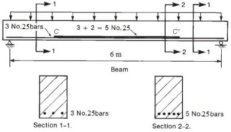
Development length in flexural reinforcement in beams
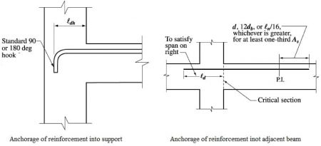
In beams, development length is provided at points of critical stress. The critical stress points in beams are Points of maximum positive and negative moments are critical sections, from which adequate anchorage ld must be provided.
Moreover, critical points are also at points within the span where adjacent reinforcement cut off; continuing bars must have adequate anchorage ld from the theoretical cut-off points of terminated bars.
Added to that, cut off bars shall extend beyond the theoretical cut-off points to resist flexure for a distance equal to d or 12db.
Development of positive moment reinforcement
For simple members, minimum one-third of positive moment reinforcement and one-fourth of positive moment reinforcement in continuous members must extend along the element face into the support.
These reinforcements in beams shall extend into the support at least 152.3mm.
Development of negative moment reinforcement
Negative moment reinforcement in a continuous, restrained, or cantilever member, or in any member of a rigid frame, shall be anchored in or through the supporting member by embedment length, hooks, or mechanical anchorage.
Additionally, at least one-third the total tension reinforcement provided for negative moment at a support shall have an embedment length beyond the point of inflection not less than d, 12db, or clear span /16, whichever is greater.
