A Technique, not a Finish According to Bob Flexner's "Understanding Wood Finishing", French polishing refers to a technique for applying shellac, not a finish in and of itself. Essentially you apply a very large number of thin coats of shellac using a pad, a wee bit of oil, and a lot of elbow grease. There's no need to get too caught up in the 'right' way of doing it. Like anything in life, with ample practice your French polished pieces will look better and better, and you'll work out a sequence of steps that suit you best.
Do keep in mind that while a French polished surface has a high water vapour resistance, it has relatively low abrasion resistance. So it's best used for pieces that won't get a lot of heavy use, or be subject to water or alcohol spills.
What You Need
French polishing doesn't require much in the way of materials. You'll need some freshly made shellac (begin with a 1-pound cut which is thinner and easier to apply; later you can use a 2-pound cut if you want to speed up your finishing); a rubbing pad, and some mineral oil (which keeps the rubbing pad from sticking to the freshly applied shellac). If you're using pre-mixed shellac remember that it's likely a 3-pound cut, so you'll want to thin it by adding some alcohol (methyl hydrate or mineral spirits will do). Because you only need to apply a bit of shellac at a time, things go easier if you pour some shellac into a squeeze bottle (old mustard bottles work great; it's also a convenient way to dispense the alcohol). To make a rubbing pad you'll need some lint-free cotton, or linen, for the 'cover' (about 8" by 8") and some cotton, wool, or cheesecloth for the 'core'. Make a wad about the size of a tennis ball with the core material, and then wrap the cover over it, ensuring that the bottom of your pad is smooth. Before using a new pad you can 'condition' it by delivering a couple of good squirts of shellac onto the core of the pad. Store the pad in a jar or zip lock bag when not in use, as you don't want to let it completely dry out. When the cover material gets dirty or torn just replace it; the core will last for ages. You'll be exerting a lot of pressure when applying the shellac, so it's a good idea to secure your work piece to your work surface (I used padded battens).
Fill the Pores For wood with small pores, such as maple or cherry, you go straight to work with the shellac. For large pored woods, such as oak or walnut, the finish will look smoother and glossier if you fill the pores. The easiest and quickest way to fill the pores is to brush on consecutive coats of shellac, sanding between coats, until the pores are filled. If you're a purist and want to fill the pores the old fashioned way, you can read about it in Flexner's book. On darker woods, like cherry, I lay a thin coat of boiled linseed oil on the surface before filling the pores, to increase the depth of the finish.
Rub On When you are ready to apply the shellac, squirt enough shellac onto the pad to dampen it (damp, but not 'sodden'). This process is called 'charging your pad'. Then give it the traditional 'French kiss' (smack the pad against the palm of your hand) and you're ready to go.
The first step is called 'bodying'. Three things to keep in mind at this stage: 1) keep the pad moving. If you let it sit on the surface it will stick; 2) once you've padded over an area, wait until it's dry before going back over. If you don't do this, your pad will stick; and 3) begin with light pressure then increase pressure as you polish. Good lighting is important so that you can see whether you're applying the shellac consistently across the whole work surface.
Begin your bodying by pressing the pad on the work surface and simultaneously begin moving in circles or figure '8s'. No need to go too fast, just keep your pad moving. As you start to feel some resistance when moving the pad, apply more downward pressure. When you start to feel a lot of resistance, it's time to lift the pad off the surface. Add another squirt of shellac, plus a drop of mineral oil, which you’ll add, each time you recharge your pad with shellac from now on. Give it the French kiss, then rub on. Once you begin adding the mineral oil, you will begin to notice streaks (called 'clouds') of oil on the surface. You will remove those clouds later.
Remember that shellac dries pretty quickly, so by the time you've applied one coat it's dry enough for the second coat. The idea is to lay down as may coats as it takes to make the surface look smooth and level. And don't forget those edges. You don't have to complete the polishing all at one go. Try applying six or seven coats then let it dry overnight. That will give the shellac time to cure. Lay on another six or seven coats the next day, and so on. You've completed this stage when you've built up a mirror like finish on the surface.
The next step is called 'spiriting' or 'clearing'. It consists of removing the oil that's still left on the surface. It's a good idea to let the shellac cure for a few days before you clear off the oil. The traditional way is to use alcohol. Make a new polishing pad and charge it with a few drops of alcohol. Use the pad in a sweeping motion across the wood surface: begin on one side of the surface like an airplane coming in for a landing, sweep across the surface, then lift it off at the other edge, like a plane taking off. Continue until you have a glossy sheen. Be careful not to damage the shellac by rubbing too hard. A quicker and easier way to remove the oil is simply to wipe the surface with naphtha (camp stove fuel).
The final step is to apply a wax and buff it out.
French polishing isn't for everyone. But, like Alexander Keith's Pale Ale: people who like it, like it a lot!
There are three types of polish:
Natural polish: This will leave the natural color of the wood underneath. ...
Color polish: As the name suggests, this will match the color of the laminate. ...
Melamine polish: After the color polish, melamine is sprayed on the surface to make it last longer.
Surface finishes absorb the brunt of contact so the wood is protected. The most common types are lacquer, shellac, polyurethane, varnish and wax.
Since 19th-century French polishing technique is in use. It is a classic technique of wood finishing. It is a mixture of shellac and alcohol. A rubbing pad lubricated with oil is used for the application of this finish on the wooden surface. It gives the glossiest appearance to the wooden surface.
Concrete is a construction material composed of cement, fine aggregates (sand) and coarse aggregates mixed with water which hardens with time. Portland cement is the commonly used type of cement for production of concrete. Concrete technology deals with study of properties of concrete and its practical applications.
In a building construction, concrete is used for the construction of foundations, columns, beams, slabs and other load bearing elements.
There are different types of binding material is used other than cement such as lime for lime concrete and bitumen for asphalt concrete which is used for road construction.
Various types of cements are used for concrete works which have different properties and applications. Some of the type of cement are Portland Pozzolana Cement (PPC), rapid hardening cement, Sulphate resistant cement etc.
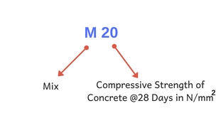
Materials are mixed in specific proportions to obtain the required strength. Strength of mix is specified as M5, M10, M15, M20, M25, M30 etc, where M signifies Mix and 5, 10, 15 etc. as their strength in kN/m2. In United States, concrete strength is specified in PSI which is Pounds per Square Inch. Water cement ratio plays an important role which influences various properties such as workability, strength and durability. Adequate water cement ratio is required for production of workable concrete.
When water is mixed with materials, cement reacts with water and hydration reaction starts. This reaction helps ingredients to form a hard matrix that binds the materials together into a durable stone-like material.
Concrete can be casted in any shape. Since it is a plastic material in fresh state, various shapes and sizes of forms or formworks are used to provide different shapes such as rectangular, circular etc.
Various structural members such as beams, slabs, footings, columns, lintels etc. are constructed with concrete.
ACI 318 Building code requirements for structural concrete and ACI 301 Specifications for Structural Concrete are used in United States as standard code of practice for concrete construction.
There are different types of admixtures which are used to provide certain properties. Admixtures or additives such as pozzolans or superplasticizers are included in the mixture to improve the physical properties of the wet mix or the finished material.
Various types of concrete are manufactured these days for construction of buildings and structures. These have special properties and features which improve quality of construction as per requirement.
Components of Concrete
Components of concrete are cement, sand, aggregates and water. Mixture of Portland cement and water is called as paste. So, concrete can be called as a mixture of paste, sand and aggregates. Sometimes rocks are used instead of aggregates.
The cement paste coats the surface of the fine and coarse aggregates when mixed thoroughly and binds them. Soon after mixing the components, hydration reaction starts which provides strength and a rock solid concrete is obtained.
What is Grade of Concrete?
Grade of concrete denotes its strength required for construction. For example, M30 grade signifies that compressive strength required for construction is 30MPa. The first letter in grade “M” is the mix and 30 is the required strength in MPa.
Based on various lab tests, grade of concrete is presented in Mix Proportions. For example, for M30 grade, the mix proportion can be 1:1:2, where 1 is the ratio of cement, 1 is the ratio of sand and 2 is the ratio of coarse aggregate based on volume or weight of materials.
The strength is measured with concrete cube or cylinders by civil engineers at construction site. Cube or cylinders are made during casting of structural member and after hardening it is cured for 28 days. Then compressive strength test is conducted to find the strength.
Regular grades of concrete are M15, M20, M25 etc. For plain cement concrete works, generally M15 is used. For reinforced concrete construction minimum M20 grade of concrete are used.
Concrete Grade
Mix Ratio
Compressive Strength
MPa (N/mm2)
psi
Normal Grade of Concrete
M5
1 : 5 : 10
5 MPa
725 psi
M7.5
1 : 4 : 8
7.5 MPa
1087 psi
M10
1 : 3 : 6
10 MPa
1450 psi
M15
1 : 2 : 4
15 MPa
2175 psi
M20
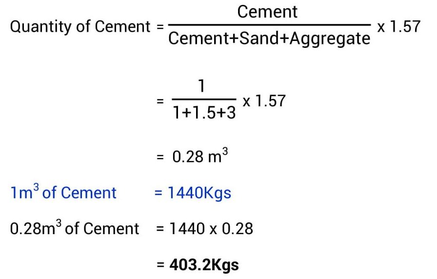
1 : 1.5 : 3
20 MPa
2900 psi
Standard Grade of Concrete
M25
1 : 1 : 2
25 MPa
3625 psi
M30
Design Mix
30 MPa
4350 psi
M35
Design Mix
35 MPa
5075 psi
M40
Design Mix
40 MPa
5800 psi
M45
Design Mix
45 MPa
6525 psi
High Strength Concrete Grades
M50
Design Mix
50 MPa
7250 psi
M55
Design Mix
55 MPa
7975 psi
M60
Design Mix
60 MPa
8700 psi
M65
Design Mix
65 MPa
9425 psi
M70
Design Mix
70 MPa
10150 psi
How to Make Concrete?
Concrete is manufactured or mixed in proportions w.r.t. cement quantity. There are two types of concrete mixes, i.e. nominal mix and design mix. Nominal mix is used for normal construction works such as small residential buildings. Most popular nominal mix are in the proportion of 1:2:4. Design mixed concrete are those for which mix proportions are finalized based on various lab tests on cylinder or cube for its compressive strength. This process is also called as mix design. These tests are conducted to find suitable mix based on locally available material to obtain strength required as per structural design. A design mixed offers economy on use of ingredients.
Once suitable mix proportions are known, then its ingredients are mixed in the ratio as selected. Two methods are used for mixing, i.e. Hand Mixing or Machine Mixing.
Based on quantity and quality required, the suitable method of mixing is selected. In the hand mixing, each ingredients are placed on a flat surface and water is added and mixed with hand tools. In machine mixing, different types of machines are used. In this case, the ingredients are added in required quantity to mix and produce fresh concrete.
Once the it is mixed adequately it is transported to casting location and poured in formworks. Various types of formworks are available which as selected based on usage.
Poured concrete is allowed to set in formworks for specified time based on type of structural member to gain sufficient strength.
After removal of formwork, curing is done by various methods to make up the moisture loss due to evaporation. Hydration reaction requires moisture which is responsible for setting and strength gain. So, curing is generally continued for minimum 7 days after removal of formwork.
Types of Concrete Construction
Concrete is generally used in two types of construction, i.e. plain concrete construction and reinforced concrete construction. In PCC, it is poured and casted without use of any reinforcement. This is used when the structural member is subjected only to the compressive forces and not bending.
When a structural member is subjected to bending, reinforcements are required to withstand tension forces structural member as it is very weak in tension compared to compression. Generally, strength of concrete in tension is only 10% of its strength in compression.
It is used as a construction material for almost all types of structures such as residential concrete buildings, industrial structures, dams, roads, tunnels, multi storey buildings, skyscrapers, bridges, sidewalks and superhighways etc.
Example of famous and large structures made with concrete are Hoover Dam, Panama Canal and Roman Pantheon. It is the largest human made building materials used for construction.
Concrete is an artificial stone-like material used for various structural purposes. It is made by mixing a binding material (as cement) and various aggregates (inert materials), such as sand, stone chips, brick chips, brick chips, pebbles, gravel, shale, etc with water and allowing the mixture to harden by hydration.
Basic advantages and disadvantages of concrete are as follows.
Advantages of Concrete
Some advantages of concrete are given below in brief.
Concrete is economical when ingredients are readily available.
Concrete’s long life and relatively low maintenance requirements increase its economic benefits.
It is not as likely to rot, corrode, or decay as other building materials.
Concrete has the ability to be molded or cast into almost any desired shape.
Building of the molds and casting can occur on the work-site which reduces cost.
Concrete is a non-combustible material which makes it fire-safe and able to withstand high temperatures.
It is resistant to wind, water, rodents, and insects. Hence, concrete is often used for storm shelters.
Disadvantages of Concrete
Concrete has some disadvantages too along the advantages stated above.
Concrete has a relatively low tensile strength (compared to other building materials),
low ductility,
low strength-to-weight ratio, and
Concrete is susceptible to cracking.
Concrete remains the material of choice for many applications regardless of these limitations.
Following are the different types of cement used in construction works.
1. Rapid Hardening Cement:
Rapid hardening cement is very similar to ordinary portland cement (OPC). It contains higher c3s content and finer grinding. Therefore it gives greater strength development at an early stage than OPC. The strength of this cement at the age of 3 days is almost same as the 7 days strength of OPC with the same water-cement ratio. The main advantage of using rapid hardening cement is that the formwork can be removed earlier and reused in other areas which save the cost of formwork. This cement can be used in prefabricated concrete construction, road works, etc.
2. Low Heat Cement:
Low heat cement is manufactured by increasing the proportion of C2S and by decreasing the C3S and C3A content. This cement is less reactive and its initial setting time is greater than OPC. This cement is mostly used in mass concrete construction.
3. Sulfate Resisting Cement:
Sulfate resisting cement is made by reducing C3A and C4AF content. Cement with such composition has excellent resistance to sulfate attack. This type of cement is used in the construction of foundation in soil where subsoil contains very high proportions of sulfate .
4. White Cement:
White cement is a type of ordinary Portland Cement which is pure white in color and has practically the same composition and same strength as OPC. To obtain the white color the iron oxide content is considerably reduced. The raw materials used in this cement are limestone and china clay. This cement, due to its white color, is mainly used for interior and exterior decorative work like external renderings of buildings, facing slabs, floorings, ornamental concrete products, paths of gardens, swimming pools etc.
5. Portland Pozzolana Cement:
Portland pozzolana cement is produced either by grinding together, portland cement clinkers and pozzolana with the addition of gypsum or calcium sulfate or by intimately and uniformly blending portland cement and fine pozzolana. It produces lower heat of hydration and has greater resistance to attack of chemical agencies than OPC. Concrete made with PPC is thus considered particularly suitable for construction in sea water, hydraulic works and for mass concrete works.
6. Hydrophobic Cement:
Hydrophobic cement is manufactured by adding water repellant chemicals to ordinary portland cement in the process of grinding. Hence the cement stored does not spoiled even during monsoon. This cement is claimed to remain unaffected when transported during rains also. Hydrophobic cement is mainly used for the construction of water structures such dams, water tanks, spillways, water retaining structures etc.
7. Colored Cement:
This Cement is produced by adding 5- 10% mineral pigments with portland cement during the time of grinding. Due to the various color combinations, this cement is mainly used for interior and exterior decorative works.
8. Waterproof Portland Cement:
Waterproof cement is prepared by mixing with ordinary or rapid hardening cement, a small percentage of some metal stearates (Ca, Al, etc) at the time of grinding. This cement is used for the construction of water-retaining structure like tanks, reservoirs, retaining walls, swimming pools, dams, bridges, piers etc.
9. Portland Blast Furnace Cement:
In this case, the normal cement clinkers are mixed with up to 65% of the blast furnace slag for the final grinding. This type of cement can be used with advantage in mass concrete work such as dams, foundations, and abutments of bridges, retaining walls , construction in sea water.
10. Air Entraining Cement:
It is produced by air entraining agents such as resins, glues, sodium salts of sulfate with ordinary portland cement.
11. High Alumina Cement:
High alumina cement (HAC) is a special cement, manufactured by mixing of bauxite ( aluminum ore) and lime at a certain temperature. This cement is also known as calcium aluminum cement (CAC). The compressive strength of this cement is very high and more workable than ordinary portland cement.
12. Expansive Cement:
The cement which does not shrink during and after the time of hardening but expands slightly with time is called expansive cement. This type of cement is mainly used for grouting anchor bolts and prestressed concrete ducts.
There are different types of cement used in construction works. Ordinary portland cement is most widely used cement among them. Portland cement is graded according to their strength where the grade denotes the compression strength of concrete that will achieve after setting of 28 days in MPa (Mega Pascals) or in N/mm2.
Compression Strength:
The compression strength of 43 grade cement is 43 MPa after 28 days of setting and the compression strength of 53 grade cement is 53 MPa after 28 days of setting.
Initial Strength:
53 graded cement is mostly used in fast forward construction where initial strength needs to be achieved quickly.
53 grade cement has faster setting compared to 43 grade cement. Compression strength of 53 grade cement after 7 days is 27 MPa but 43 grade cement gets 23 MPa after 7 days.
Uses And Application:
As 53 grade cement has a faster setting, it is used where earlier strength development is required such as reinforced concrete structures, cement grouts, prestressed concrete structures of higher grades, instant plugging mortars etc.
43 grade cement is used in non-RCC structures, plastering works, pathways etc where initial setting time is not a criteria.
Aggregate is a granular material, such as sand, gravel, crushed stone, crushed hydraulic-cement concrete, or iron blast-furnace slag, used with a hydraulic cementing medium to produce either concrete or mortar.
Coarse Aggregate
Those particles that are predominantly retained on the 4.75 mm (No. 4) sieve and will pass through 3-inch screen, are called coarse aggregate. The coarser the aggregate, the more economical the mix. Larger pieces offer less surface area of the particles than an equivalent volume of small pieces. Use of the largest permissible maximum size of coarse aggregate permits a reduction in cement and water requirements. Using aggregates larger than the maximum size of coarse aggregates permitted can result in interlock and form arches or obstructions within a concrete form. That allows the area below to become a void, or at best, to become filled with finer particles of sand and cement only and results in a weakened area.
Fine Aggregate
Those particles passing the 9.5 mm (3/8 in.) sieve, almost entirely passing the 4.75 mm (No. 4) sieve, and predominantly retained on the 75 µm (No. 200) sieve are called fine aggregate. For increased workability and for economy as reflected by use of less cement, the fine aggregate should have a rounded shape. The purpose of the fine aggregate is to fill the voids in the coarse aggregate and to act as a workability agent.
In concrete, an aggregate is used for its economy factor, to reduce any cracks and most importantly to provide strength to the structure. In roads and railway ballast, it is used to help distribute the load and assist in ground water running off the road.
Increases the volume of concrete, thus reduces the cost
Provide dimensional stability
Influence hardness, abrasion resistance, elastic modulus and other properties of concrete to make it more durable, strong and cheaper.
Source:-www.aboutcivil.org
WHAT ARE THE PROPERTIES OF AGGREGATES FOR CONCRETE?
Aggregates are used in concrete to provide economy in the cost of concrete. Aggregates act as filler only. These do not react with cement and water.
But there are properties or characteristics of aggregate which influence the properties of resulting concrete mix. These are as follow.
Composition
Size & Shape
Surface Texture
Specific Gravity
Bulk Density
Voids
Porosity & Absorption
Bulking of Sand
Fineness Modulus of Aggregate
Surface Index of Aggregate
Deleterious Material
Crushing Value of Aggregate
Impact Value of Aggregate
Abrasion Value of Aggregate
1. Composition
Aggregates consisting of materials that can react with alkalies in cement and cause excessive expansion, cracking and deterioration of concrete mix should never be used. Therefore it is required to test aggregates to know whether there is presence of any such constituents in aggregate or not.
2. Size & Shape
The size and shape of the aggregate particles greatly influence the quantity of cement required in concrete mix and hence ultimately economy of concrete. For the preparation of economical concrete mix on should use largest coarse aggregates feasible for the structure. IS-456 suggests following recommendation to decide the maximum size of coarse aggregate to be used in P.C.C & R.C.C mix.
Maximum size of aggregate should be less than
One-fourth of the minimum dimension of the concrete member.
One-fifth of the minimum dimension of the reinforced concrete member.
The minimum clear spacing between reinforced bars or 5 mm less than the minimum cover between the reinforced bars and form, whichever is smaller for heavily reinforced concrete members such as the ribs of the main bars.
Remember that the size & shape of aggregate particles influence the properties of freshly mixed concrete more as compared to those of hardened concrete.
The development of hard bond strength between aggregate particles and cement paste depends upon the surface texture, surface roughness and surface porosity of the aggregate particles.
If the surface is rough but porous, maximum bond strength develops. In porous surface aggregates, the bond strength increases due to setting of cement paste in the pores.
4. Specific Gravity
The ratio of weight of oven dried aggregates maintained for 24 hours at a temperature of 100 to 1100C, to the weight of equal volume of water displaced by saturated dry surface aggregate is known as specific gravity of aggregates.
Specific gravities are primarily of two types.
Apparent specific gravity
Bulk specific gravity
Specific gravity is a mean to decide the suitability of the aggregate. Low specific gravity generally indicates porous, weak and absorptive materials, whereas high specific gravity indicates materials of good quality. Specific gravity of major aggregates falls within the range of 2.6 to 2.9.
Specific gravity values are also used while designing concrete mix.
5. Bulk Density
It is defined as the weight of the aggregate required to fill a container of unit volume. It is generally expressed in kg/litre.
Bulk density of aggregates depends upon the following 3 factors.
Degree of compaction
Grading of aggregates
Shape of aggregate particles
6. Voids
The empty spaces between the aggregate particles are known as voids. The volume of void equals the difference between the gross volume of the aggregate mass and the volume occupied by the particles alone.
7. Porosity & Absorption
The minute holes formed in rocks during solidification of the molten magma, due to air bubbles, are known as pores. Rocks containing pores are called porous rocks.
Water absorption may be defined as the difference between the weight of very dry aggregates and the weight of the saturated aggregates with surface dry conditions.
Depending upon the amount of moisture content in aggregates, it can exist in any of the 4 conditions.
Very dry aggregate ( having no moisture)
Dry aggregate (contain some moisture in its pores)
Saturated surface dry aggregate (pores completely filled with moisture but no moisture on surface)
Moist or wet aggregates (pores are filled with moisture and also having moisture on surface)
8. Bulking of Sand
It can be defined as in increase in the bulk volume of the quantity of sand (i.e. fine aggregate) in a moist condition over the volume of the same quantity of dry or completely saturated sand. The ratio of the volume of moist sand due to the volume of sand when dry, is called bulking factor.
Fine sands bulk more than coarse sand
When water is added to dry and loose sand, a thin film of water is formed around the sand particles. Interlocking of air in between the sand particles and the film of water tends to push the particles apart due to surface tension and thus increase the volume. But in case of fully saturated sand the water films are broken and the volume becomes equal to that of dry sand.
9. Fineness Modulus
Fineness modulus is an empirical factor obtained by adding the cumulative percentages of aggregate retained on each of the standard sieves ranging from 80 mm to 150 micron and dividing this sum by 100.
Fineness modulus is generally used to get an idea of how coarse or fine the aggregate is. More fineness modulus value indicates that the aggregate is coarser and small value of fineness modulus indicates that the aggregate is finer.
10. Specific Surface of Aggregate
The surface area per unit weight of the material is termed as specific surface. This is an indirect measure of the aggregate grading. Specific surface increases with the reduction in the size of aggregate particle. The specific surface area of the fine aggregate is very much more than that of coarse aggregate.
11. Deleterious Materials
Aggregates should not contain any harmful material in such a quantity so as to affect the strength and durability of the concrete. Such harmful materials are called deleterious materials. Deleterious materials may cause one of the following effects
To interfere hydration of cement
To prevent development of proper bond
To reduce strength and durability
To modify setting times
Deleterious materials generally found in aggregates, may be grouped as under
Organic impurities
Clay , silt & dust
Salt contamination
12. Crushing Value
The aggregates crushing value gives a relative measure of resistance of an aggregate to crushing under gradually applied compressive load. The aggregate crushing strength value is a useful factor to know the behavior of aggregates when subjected to compressive loads.
13. Impact Value
The aggregate impact value gives a relative measure of the resistance of an aggregate to sudden shock or impact. The impact value of an aggregate is sometime used as an alternative to its crushing value.
14. Abrasion Value of Aggregates
The abrasion value gives a relative measure of resistance of an aggregate to wear when it is rotated in a cylinder along with some abrasive charge.
Different types of the admixtures are used in concrete construction.
1: Accelerators:
Setting time was reduced by the use of the accelerator and generally produce an early setting of concrete repair and patch work. In the cold weathers accelerators was used to achieve the early strength.
The calcium chloride (CaCl2) is the most common accelerator which was used in the plain cement concrete work. The quantity of calcium chloride is limited in a concrete mix is about 1%-2% by weight of cement.
The Main properties of accelerator were
1: Shortening setting time
2: Increase early strength
3: Aids, cold weather concreting
2: Retarders:
The function of reader is opposite to the accelerator. The retarder increase the setting time of concrete. By the use of retarder the water cement ratio was reduced.
Usually by the use of this admixture the water was reduced at about 10%. Various types of water, reducing agents and set-retarding admixtures was used in Ready mix concrete.The chemical are, 1: Lignosulphonic Acid and their salts. 2: Hydroxylated carboxylic acid and their salts. 3: Sulphonated melamine. 4: naphthalene formaldehyde.
They also have a detergent like properties.
3: Plasticizers:
The plasticizer is the admixture which was added in fresh concrete to increase it’s workability. Three main types of the plasticizers were used such as
1: Finely divided minerals (Either cementitious or pozzolanic)
2: Air-entertaining agents (Produces discontinuous air bubbles)
3: Synthetic derivatives (Produce soapy action)
4: Superplasticizers:
Extreme work ability of concrete was achieved by the use of superplasticizer. The reduction, water cement ratio was done without loss of work ability. The use of superplasticizer leads to the reduction of overall cost.
For extreme work ability the electrochemical activities were responsible. The increase of the mobility of concrete the concrete starts to flow without segregation.
Superplasticizer enable the saving in the cement and make the concrete ideal for pumping, Casting heavily reinforced concrete members and precast elements of concrete.
5: Waterproofers:
This type of admixtures was added in concrete to make the structure water proof. These chemicals react with lime, which is present in cement to form inorganic salts which blocks the pores and capillaries, thereby reducing moisture penetration.
Waterproofers may obtained in liquid and in powder form and consist of pore filling or water- repellent materials.
The chief material for a pore – filling are 1: Alkali silicated. 2: Notably silicates. 3: Zinc sulfates.. 4: Chlorides of aluminium and calcium.
6: Miscellaneous Admixtures:
Many other chemical admixtures were used in concrete to achieve results such as 1: Gas-Forming and Expansive chemicals 2: Corrosion-Inhibiting Chemicals 3: Pigments 4: Antifungal admixtures 5: Curing compounds 6: sealants 7: Flooring 8: Floor coating 9: Guniting Aids
7: Mineral Admixtures:
To modify the concrete properties, mineral admixtures was used under the permits of IS: 456-2000. Those are 1: Fly Ash 2: Silica Fume 3: Rice Husk Ash 4: Metakaoline 5: Ground Granulated Blast Furnace slag.
The following materials may added in concrete either as a admixture or as a part of cement.
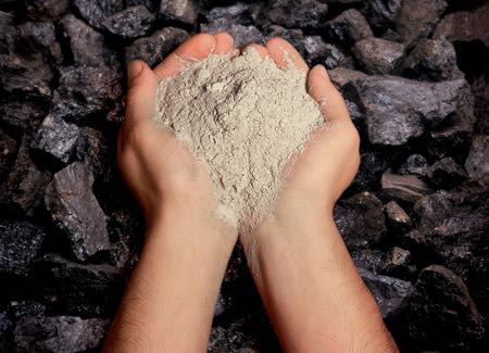
A simple everyday definition of 'pozzolan' could be 'a finely powdered material which can be added to lime mortar (or to Portland cement mortar) to increase durability. A more formal definition is given by ASTM C618-84 as 'a siliceous or siliceous and aluminous material which, in itself, possesses little or no cementitious value but which will, in finely divided form in the presence of moisture, react chemically with calcium hydroxide at ordinary temperature to form compounds possessing cementitious properties'
==================================
Sources and Types of Pozzolanic Material
Pozzolanic materials can be divided into the categories listed below, according to their origin and properties.
Natural, Very Finely Divided, Highly Reactive Materials of Volcanic Origin:
These materials are formed from a combination of minerals, (mainly consisting of silica and alumina with smaller and variable quantities of other minerals containing calcium, magnesium, iron, potassium, and sodium), ejected from volcanoes in the form of very finely divided vitreous material. Other vitreous volcanic material, such as basalt, may have mild pozzolanic properties if very finely ground.
These natural pozzolans were widely used in 19th century engineering works in conjunction with natural hydraulic limes. They were recognized as being particularly appropriate for marine engineering and other works in difficult wet conditions, and for civil engineering works generally. Well known sources include puozzolana from Puozzoli in Italy, volvic pozzolan from South-east France, trass from the Rhineland and tuff from the Aegean islands. Crushed pumice was also used.
Low Temperature Calcined Clay Products In Various Forms
Pozzolanic additives derived from lightly fired and finely crushed clay products, such as clay tile or brick, were used by the Romans and combinations of non-hydraulic lime and low temperature brick dusts have been used over a long period of time. Similar specifications are successfully employed in modern conservation practice where additional set and durability are required without seriously reducing the permeability and flexibility of the mortar.
Bodies such as English Heritage have promoted the use, particularly for conservation work, of low temperature clay pozzolans in non-hydraulic mortars. Current advice is that the material should be derived from clay fired at temperatures below 950 °C, and ground to a range of particle sizes between 38 and 600 microns.Modern sources of potentially suitable material include reject bricks and tiles from traditional producers, which can be crushed in a roller pan mill. Some manufacturers also produce low temperature purpose-made dusts for sale as pozzolans.
Clay or Kaolin Products Specifically Manufactured as Pozzolans
These are produced primarily for use with Portland cement and all currently available technical and performance data relates to their use in that context. These materials are highly reactive and combine readily with calcium hydroxide to form calcium silicate hydrates and calcium alumino-silicate hydrates. Their effect on the performance and characteristics of lime mortars is not currently known but, subject to adequate investigation and trials, it is possible that their use could be extended into this field.
Also falling into the category of fired clays is the material known as HTI (high temperature insulation) powder. This was widely specified in the 1980s but has now largely been superseded by lower temperature materials which are thought to be more consistent in their performance.
Mineral Slag:
Furnace slag is a vitrified material, produced as a by-product of processes such as smelting, and requires grinding to convert it to a reactive material. It contains silica, alumina, lime and other minerals in various proportions and, in modern practice, is more commonly used as an additive in Portland cement concretes. Historically, forge scale and iron-rich slag, known as minion, were also used.
Ashes of Organic Origin:
Coal cinders generally have an acceptable balance of silica and alumina, and have been used historically as a pozzolanic additive, but their physical structure tends to weaken the mortar and to absorb excessive water. Coal ash is widely used, in the form of PFA (pulverised fuel ash) as an additive to cementitious mortars and in lime-based grouts. The use of coal-based products carries a risk of sulphate contamination and the materials should always be selected from low sulphate coals. The residue of fuels from lime burning, whether from coal-, coke-, or wood-fired kilns, known as lime-ash, is well known historically as a pozzolan and is still available. Other vegetable ashes, such as rice husk ash, are used as pozzolans in other parts of the world. Bone ash is also known to have been used.
Certain Natural Sands and Crushed Rock Products:
Certain types of sand, such as argillaceous (clayey) sands containing high proportions of schist, basalt, feldspar and mica, can have mildly pozzolanic properties. Whilst these sands are not generally specified for modern lime-based mortars it may be useful to recognize that, historically, in certain localities, their use could have influenced the nature of local lime mortars. Finely crushed rock products from sources containing an appropriate balance of minerals may also produce a mild pozzolanic effect. Traditionally, mortars were often produced using techniques which brought the sand into contact with hot slaking lime, and it is possible that this heat would have encouraged any potential for a mild pozzolanic reaction between sand and lime.
Generally, quality of water for construction works are same as drinking water. This is to ensure that the water is reasonably free from such impurities as suspended solids, organic matter and dissolved salts, which may adversely affect the properties of the concrete, especially the setting, hardening, strength, durability, pit value, etc.
The water shall be clean and shall not contain sugar, molasses or gur or their derivatives, or sewage, oils, organic substances.
If the quality of water to be used for mixing is in doubt, cubes of 75 mm in cement mortar 1:3 mix with distilled water and with the water in question shall be made separately. The latter type of cubes should attain 90% of the 7 days’ strength obtained in cubes with same quantity of distilled water.
Alternatively, the water shall be tested in an approved Laboratory for its use in preparing concrete / mortar.
The water quality for construction shall be tested or monitored regularly, as it affects the overall strength of concrete. For plain and reinforced cement concrete permissible limits for solids shall be as follows:
Type of Solid in water
Permissible Limits for Construction
Organic matter
200 mg/l
Inorganic matter
3000 mg/l
Sulphates (SO4)
500 mg/l
Chlorides (Cl)
a) 1000 mg/l for RCC work and, b) 2000 mg/l for PCC work
Suspended matter
2000 mg/l
Limits of Alkalinity:
To neutralize 200 ml of sample should not require more than 10 ml of 0.1 normal HCI using methyl orange as an indicator.
Limits of Acidity:
To neutralize 200 ml sample of water should not require more than 2 m of 0.1 normal NaOH (Caustic soda). The pH value of water shall generally be not less than 6.
Water Cement Ratio and Abrams' law
Mohammed Zaid
Posted on : 14 Mar 2016
Duff Abrams published data that showed that for a given set of concreting materials, the strength of the concrete depends solely on the relative quantity of water compared with the cement. In other words, the strength is a function of the water to cement ratio (w/c) where w represents the mass of water and c represents the mass of cement. This became known as Abrams law and it remains valid today as it was in 1918. However, more often, w/cm is used and cm represents the mass of cementing materials, which includes the portland cement plus any supplementary cementing materials such as fly ash, slag cement, or silica fume.
Unnecessarily high water content dilutes the cement paste (the glue of concrete) and increases the volume of the concrete produced. Some advantages of reducing water content include:
Increased compressive and flexural strength
Lower permeability and increased watertightness
Increased durability and resistance to weathering
Better bond between concrete and reinforcement
Reduced drying shrinkage and cracking
Less volume change from wetting and drying
The less water used, the better the quality of the concrete provided themixture can still be consolidated properly.
Smaller amounts of mixing water result in stiffer mixtures; with vibration, stiffer mixtures can be easily placed. Thus, consolidation by vibration permits improvement in the quality of concrete.
Reducing the water content of concrete, and thereby reducing the w/cm, leads to increased strength and stiffness, and reduced creep. The drying shrinkage and associated risk of cracking will also be reduced. The concrete will have a lower permeability or increased water tightness that will render it more resistant to weathering and the action of aggressive chemicals. The lower water to cementitious materials ratio also improves the bond between the concrete and embedded steel reinforcement.
Properties of concrete are influenced by many factors mainly due to mix proportion of cement, sand, aggregates and water. Ratio of these materials control the various concrete properties which are discussed below.
Properties of Concrete
Different properties of concrete:
Grades (M20, M25, M30 etc.)
Compressive strength
Characteristic Strength
Tensile strength
Durability
Creep
Shrinkage
Unit weight
Modular Ratio
Poisson’s ratio
1. Grades of concrete
Concrete is known by its grade which is designated as M15, M20 etc. in which letter M refers to concrete mix and number 15, 20 denotes the specified compressive strength (fck) of 150mm cube at 28 days, expressed in N/mm2.
Thus, concrete is known by its compressive strength. M20 and M25 are the most common grades of concrete, and higher grades of concrete should be used for severe, very severe and extreme environments.
2. Compressive strength of concrete
Like load, the strength of the concrete is also a quality which varies considerably for the same concrete mix. Therefore, a single representative value, known as characteristic strength is used.
3. Characteristic strength of concrete
It is defined as the value of the strength below which not more then 5% of the test results are expected to fall (i.e. there is 95% probability of achieving this value only 5% of not achieving the same)
Characteristic strength of concrete in flexural member
The characteristic strength of concrete in flexural member is taken as 0.67 times the strength of concrete cube.
Design strength (fd) and partial safety factor for material strength
The strength to be taken for the purpose of design is known is known as design strength and is given by
Design strength (fd) = characteristic strength/ partial safety factor for material strength
The value of partial safety factor depends upon the type of material and upon the type of limit state. According to IS code, partial safety factor is taken as 1.5 for concrete and 1.15 for steel.
Design strength of concrete in member = 0.45fck
4. Tensile strength of concrete
The estimate of flexural tensile strength or the modulus of rupture or the cracking strength of concrete from cube compressive strength is obtained by the relations
fcr = 0.7 fck N/mm2. The tensile strength of concrete in direct tension is obtained experimentally by split cylinder. It varies between 1/8 to 1/12 of cube compressive strength.
5. Creep in concrete
Creep is defined as the plastic deformation under sustained load. Creep strain depends primarily on the duration of sustained loading. According to the code, the value of the ultimate creep coefficient is taken as 1.6 at 28 days of loading.
6. Shrinkage of Concrete
The property of diminishing in volume during the process of drying and hardening is termed Shrinkage. It depends mainly on the duration of exposure. If this strain is prevented, it produces tensile stress in the concrete and hence concrete develops cracks.
7. Modular ratio
Short term modular ratio is the modulus of elasticity of steel to the modulus of elasticity of concrete.
Short term modular ratio = Es / Ec
Es = modulus of elasticity of steel (2 x 10 5 N/mm2)
Ec = modulus of elasticity of concrete (5000 x SQRT(fck) N/mm2)
As the modulus of elasticity of concrete changes with time, age at loading etc the modular ratio also changes accordingly. Taking into account the effects of creep and shrinkage partially IS code gives the following expression for the long term modular ratio.
Long term modular ratio (m) = 280/ (3fcbc)
Where, fcbc = permissible compressive stress due to bending in concrete in N/mm2.
8. Poisson’s ratio
Poisson’s ratio varies between 0.1 for high strength concrete and 0.2 for weak mixes. It is normally taken as 0.15 for strength design and 0.2 for serviceability criteria.
9. Durability of concrete
Durability of concrete is its ability to resist its disintegration and decay. One of the chief characteristics influencing durability of concrete is its permeability to increase of water and other potentially deleterious materials.
The desired low permeability in concrete is achieved by having adequate cement, sufficient low water/cement ratio, by ensuring full compaction of concrete and by adequate curing.
10. Unit weight of concrete
The unit weight of concrete depends on percentage of reinforcement, type of aggregate, amount of voids and varies from 23 to 26 kN/m2. The unit weight of plain and reinforced concrete as specified by IS:456 are 24 and 25 KN/m3 respectively.
Tests Applied on Concrete for Strength and Workability
This test is performed to check the consistency of freshly made concrete. The slump test is done to make sure a concrete mix is workable. The measured slump must be within a set range, or tolerance, from the target slump.
Workability of concrete is mainly affected by consistency i.e. wetter mixes will be more workable than drier mixes, but concrete of the same consistency may vary in workability. It can also be defined as the relative plasticity of freshly mixed concrete as indicative of its workability.
Tools and apparatus used for slump test (equipment):
Standard slump cone (100 mm top diameter x 200 mm bottom diameter x 300 mm high)
Small scoop
Bullet-nosed rod (600 mm long x 16 mm diameter)
Rule
Slump plate (500 mm x 500 mm)
Procedure of slump test for concrete:
Clean the cone. Dampen with water and place on the slump plate. The slump plate should be clean, firm, level and non-absorbent. Collect a sample of concrete to perform the slum test.
Stand firmly on the footpieces and fill 1/3 the volume of the cone with the sample. Compact the concrete by 'rodding' 25 times. Rodding means to push a steel rod in and out of the concrete to compact it into the cylinder, or slump cone. Always rod in a definite pattern, working from outside into the middle.
Now fill to 2/3 and again rod 25 times, just into the top of the first layer.
Fill to overflowing, rodding again this time just into the top of the second layer. Top up the cone till it overflows.
Level off the surface with the steel rod using a rolling action. Clean any concrete from around the base and top of the cone, push down on the handles and step off the footpieces.
Carefully lift the cone straight up making sure not to move the sample.
Turn the cone upside down and place the rod across the up-turned cone.
Take several measurements and report the average distance to the top of the sample.If the sample fails by being outside the tolerance (ie the slump is too high or too low), another must be taken. If this also fails the remainder of the batch should be rejected.
b) Concrete Compression Test
The compression test shows the compressive strength of hardened concrete. The compression test shows the best possible strength concrete can reach in perfect conditions. The compression test measures concrete strength in the hardened state. Testing should always be done carefully. Wrong test results can be costly. The testing is done in a laboratory off-site. The only work done on-site is to make a concrete cylinder for the compression test. The strength is measured in Megapascals (MPa) and is commonly specified as a characteristic strength of concrete measured at 28 days after mixing. The compressive strength of concrete is a measure of the concrete’s ability to resist loads which tend to crush it.
Apparatus for compression test
Cylinders (100 mm diameter x 200 mm high or 150 mm diameter x 300 mm high) (The small cylinders are normally used for most testing due to their lighter weight)
Small scoop
Bullet-nosed rod (600 mm x 16 mm)
Steel float
Steel plate
How to do Compression Test?
Procedure for compression test of concrete
Clean the cylinder mould and coat the inside lightly with form oil, then place on a clean, level and firm surface, ie the steel plate. Collect a sample.
Fill 1/2 the volume of the mould with concrete then compact by rodding 25 times. Cylinders may also be compacted by vibrating using a vibrating table.
Fill the cone to overflowing and rod 25 times into the top of the first layer, then top up the mould till overflowing.
Level off the top with the steel float and clean any concrete from around the mould.
Cap, clearly tag the cylinder and put it in a cool dry place to set for at least 24 hours.
After the mould is removed the cylinder is sent to the laboratory where it is cured and crushed to test compressive strength
Non-destructive tests of concrete is a method to obtain the compressive strength and other properties of concrete from the existing structures. This test provides immediate results and actual strength and properties of concrete structure.
The standard method of evaluating the quality of concrete in buildings or structures is to test specimens cast simultaneously for compressive, flexural and tensile strengths.
The main disadvantages are that results are not obtained immediately; that concrete in specimens may differ from that in the actual structure as a result of different curing and compaction conditions; and that strength properties of a concrete specimen depend on its size and shape.
Although there can be no direct measurement of the strength properties of structural concrete for the simple reason that strength determination involves destructive stresses, several non- destructive methods of assessment have been developed.
These depend on the fact that certain physical properties of concrete can be related to strength and can be measured by non-destructive methods. Such properties include hardness, resistance to penetration by projectiles, rebound capacity and ability to transmit ultrasonic pulses and X- and Y-rays.
These non-destructive methods may be categorized as penetration tests, rebound tests, pull-out techniques, dynamic tests, radioactive tests, maturity concept. It is the purpose of this Digest to describe these methods briefly, outlining their advantages and disadvantages.
Methods of Non-Destructive Testing of Concrete
Following are different methods of NDT on concrete:
Penetration method
Rebound hammer method
Pull out test method
Ultrasonic pulse velocity method
Radioactive methods
1. Penetration Tests on Concrete
The Windsor probe is generally considered to be the best means of testing penetration. Equipment consists of a powder-actuated gun or driver, hardened alloy probes, loaded cartridges, a depth gauge for measuring penetration of probes and other related equipment.
A probe, diameter 0.25 in. (6.5 mm) and length 3.125 in. (8.0 cm), is driven into the concrete by means of a precision powder charge. Depth of penetration provides an indication of the compressive strength of the concrete.
Although calibration charts are provided by the manufacturer, the instrument should be calibrated for type of concrete and type and size of aggregate used.
The probe test produces quite variable results and should not be expected to give accurate values of concrete strength. It has, however, the potential for providing a quick means of checking quality and maturity of in situ concrete.
It also provides a means of assessing strength development with curing. The test is essentially non-destructive, since concrete and structural members can be tested in situ, with only minor patching of holes on exposed faces.
2. Rebound Hammer Method
The rebound hammer is a surface hardness tester for which an empirical correlation has been established between strength and rebound number.
The only known instrument to make use of the rebound principle for concrete testing is the Schmidt hammer, which weighs about 4 lb (1.8 kg) and is suitable for both laboratory and field work. It consists of a spring-controlled hammer mass that slides on a plunger within a tubular housing.
The hammer is forced against the surface of the concrete by the spring and the distance of rebound is measured on a scale. The test surface can be horizontal, vertical or at any angle but the instrument must be calibrated in this position.
Calibration can be done with cylinders (6 by 12 in., 15 by 30 cm) of the same cement and aggregate as will be used on the job. The cylinders are capped and firmly held in a compression machine.
Several readings are taken, well distributed and reproducible, the average representing the rebound number for the cylinder. This procedure is repeated with several cylinders, after which compressive strengths are obtained.
The Schmidt hammer provides an inexpensive, simple and quick method of obtaining an indication of concrete strength, but accuracy of ±15 to ±20 per cent is possible only for specimens cast cured and tested under conditions for which calibration curves have been established.
The results are affected by factors such as smoothness of surface, size and shape of specimen, moisture condition of the concrete, type of cement and coarse aggregate, and extent of carbonation of surface.
3. Pull-Out Tests on Concrete
A pull-out test measures, with a special ram, the force required to pull from the concrete a specially shaped steel rod whose enlarged end has been cast into the concrete to a depth of 3 in. (7.6 cm).
The concrete is simultaneously in tension and in shear, but the force required to pull the concrete out can be related to its compressive strength.
The pull-out technique can thus measure quantitatively the in-situ strength of concrete when proper correlations have been made. It has been found, over a wide range of strengths, that pull-out strengths have a coefficient of variation comparable to that of compressive strength. Read More on Pull-Out Tests on Concrete
Limitations and Advantages
Although pullout tests do not measure the interior strength of mass concrete, they do give information on the maturity and development of strength of a representative part of it. Such tests have the advantage of measuring quantitatively the strength of concrete in place.
Their main disadvantage is that they have to be planned in advance and pull-out assemblies set into the formwork before the concrete is placed. The pull-out, of course, creates some minor damage.
The test can be non-destructive, however, if a minimum pullout force is applied that stops short of failure but makes certain that a minimum strength has been reached. This is information of distinct value in determining when forms can be removed safely.
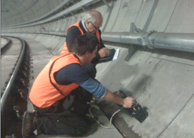
4. Dynamic Non Destructive Test
At present the ultrasonic pulse velocity method is the only one of this type that shows potential for testing concrete strength in situ. It measures the time of travel of an ultrasonic pulse passing through the concrete.
The fundamental design features of all commercially available units are very similar, consisting of a pulse generator and a pulse receiver.
Pulses are generated by shock-exciting piezoelectric crystals, with similar crystals used in the receiver. The time taken for the pulse to pass through the concrete is measured by electronic measuring circuits.
Pulse velocity tests can be carried out on both laboratory-sized specimens and completed concrete structures, but some factors affect measurement:
There must be smooth contact with the surface under test; a coupling medium such as a thin film of oil is mandatory.
It is desirable for path-lengths to be at least 12 in. (30 cm) in order to avoid any errors introduced by heterogeneity.
It must be recognized that there is an increase in pulse velocity at below-freezing temperature owing to freezing of water; from 5 to 30°C (41 – 86°F) pulse velocities are not temperature dependent.
The presence of reinforcing steel in concrete has an appreciable effect on pulse velocity. It is therefore desirable and often mandatory to choose pulse paths that avoid the influence of reinforcing steel or to make corrections if steel is in the pulse path.
The pulse velocity method is an ideal tool for establishing whether concrete is uniform. It can be used on both existing structures and those under construction.
Usually, if large differences in pulse velocity are found within a structure for no apparent reason, there is strong reason to presume that defective or deteriorated concrete is present.
High pulse velocity readings are generally indicative of good quality concrete. A general relation between concrete quality and pulse velocity is given in Table.
Table: Quality of Concrete and Pulse Velocity
General Conditions
Pulse Velocity ft/sec
Excellent
Above 15,000
Good
12,000-15,000
Questionable
10,000-12,000
Poor
7,000-10,000
Very Poor
below 7,000
Fairly good correlation can be obtained between cube compressive strength and pulse velocity. These relations enable the strength of structural concrete to be predicted within ±20 per cent, provided the types of aggregate and mix proportions are constant.
The pulse velocity method has been used to study the effects on concrete of freeze-thaw action, sulphate attack, and acidic waters. Generally, the degree of damage is related to a reduction in pulse velocity. Cracks can also be detected.
Great care should be exercised, however, in using pulse velocity measurements for these purposes since it is often difficult to interpret results. Sometimes the pulse does not travel through the damaged portion of the concrete.
The pulse velocity method can also be used to estimate the rate of hardening and strength development of concrete in the early stages to determine when to remove formwork. Holes have to be cut in the formwork so that transducers can be in direct contact with the concrete surface.
As concrete ages, the rate of increase of pulse velocity slows down much more rapidly than the rate of development of strength, so that beyond a strength of 2,000 to 3,000 psi (13.6 to 20.4 MPa) accuracy in determining strength is less than ±20%.
Accuracy depends on careful calibration and use of the same concrete mix proportions and aggregate in the test samples used for calibration as in the structure.
In summary, ultrasonic pulse velocity tests have a great potential for concrete control, particularly for establishing uniformity and detecting cracks or defects. Its use for predicting strength is much more limited, owing to the large number of variables affecting the relation between strength and pulse velocity.
5. Radioactive Methods of NDT
Radioactive methods of testing concrete can be used to detect the location of reinforcement, measure density and perhaps establish whether honeycombing has occurred in structural concrete units. Gamma radiography is increasingly accepted in England and Europe.
The equipment is quite simple and running costs are small, although the initial price can be high. Concrete up to 18 in. (45 cm) thick can be examined without difficulty.
Purpose of Non-Destructive Tests on Concrete
A variety of Non Destructive Testing (NDT) methods have been developed or are under development for investigating and evaluating concrete structures.
These methods are aimed at estimation of strength and other properties; monitoring and assessing corrosion; measuring crack size and cover; assessing grout quality; detecting defects and identifying relatively more vulnerable areas in concrete structures.
Many of NDT methods used for concrete testing have their origin to the testing of more homogeneous, metallic system. These methods have a sound scientific basis, but heterogeneity of concrete makes interpretation of results somewhat difficult.
There could be many parameters such as materials, mix, workmanship and environment, which influence the results of measurements.
Moreover, these tests measure some other property of concrete (e.g. hardness) and the results are interpreted to assess a different property of concrete e.g. strength, which is of primary interest.
Thus, interpretation of results is very important and difficult job where generalization is not possible. As such, operators can carry out tests but interpretation of results must be left to experts having experience and knowledge of application of such non-destructive tests.
Purposes of Non-destructive Tests
Estimating the in-situ compressive strength
Estimating the uniformity and homogeneity
Estimating the quality in relation to standard requirement
Identifying areas of lower integrity in comparison to other parts
Detection of presence of cracks, voids and other imperfections
Monitoring changes in the structure of the concrete which may occur with time
Identification of reinforcement profile and measurement of cover, bar diameter, etc.
Condition of prestressing/reinforcement steel with respect to corrosion
Chloride, sulphate, alkali contents or degree of carbonation
Measurement of Elastic Modulus
Condition of grouting in prestressing cable ducts
Purposes of Non-destructive Tests
Equipments for Non Destructive Testing
According to their use, non-destructive equipment can be grouped as under:
Strength estimation of concrete
Corrosion assessment and monitoring
Detecting defects in concrete structure
Laboratory tests
===================================
Chapter 6:- Concrete operations:-
Batching, Mixing, Placing and Compaction of Concrete
Batching
Batching is the process of measuring concrete mix ingredients either by volume or by mass and introducing them into the mixture. Traditionally batching is done by volume but most specifications require that batching be done by mass rather than volume. Percentage of accuracy for measurement of concrete materials as follows.
Cement:
When the quantity of cement to be batched exceeds 30% of scale capacity, the measuring accuracy should be within 1% of required mass. If measuring quantity is less than 30% i.e. for smaller batches then the measuring accuracy should be within 4% of the required quantity.
Aggregates:
If the measurement is more than 30% of the scale capacity then the measuring accuracy should be within 1%. If measurement is less than 30% then the measuring accuracy should be within less than 3%.
Water:
Water is measured in volumetric quantity as 1 litre = 1kg. In case of water, the measuring accuracy should be within 1%.
Admixtures:
For mineral admixtures same accuracy as that required for cement.For chemical admixtures same accuracy as that required for water. Mineral admixtures accuracy is same as that of cement because it is used as partial replacement of cement. As chemical admixtures are liquid or added to water therefore its accuracy is same as that of water.
Mixing
The mixing operation consists of rotation or stirring, the objective being to coat the surface the all aggregate particles with cement paste, and to blind all the ingredients of the concrete into a uniform mass; this uniformity must not be disturbed by the process of discharging from the mixer.
Batch mixer
The usual type of mixer is a batch mixer, which means that one batch of concrete is mixed and discharged before any more materials are put into the mixer. There are four types of batch mixer.
Tiltingdrummixer:
A tilting drum mixer is one whose drum in which mixing take place is tilted for discharging. The drum is conical or bowl shaped with internal vanes, and the discharge is rapid and unsegregated so that these mixers are suitable for mixes of low workability and for those containing large size aggregate.
Non tilting drum mixer:
A non tilting drum is one in which the axis of the mixer is always horizontal, and discharge take place by inserting a chute into the drum or by reversing the direction or rotation of drum. Because of slow rate of discharge, some segregation may occur.
Pan type mixer:
A pan type mixer is a forced–action mixer, as distinct from drum mixer which relies on the free fall of the concrete inside the drum. The pan mixer consist of a circular pan rotating about its axis with one or two stars paddles rotating about vertical axis of pan.
Dual drum mixer:
A dual drum is sometimes used in highway construction. Here there are two drums in series, concrete being mixed part of the time in one and then transferred to the other for the remainder of the mixing time before discharging.
Continuous mixers:
These are fed automatically by a continuous weigh-batching system.
Charging the mixer:
There are no general rules on the order of feeding the ingredients into the mixer as this depend on the properties of the mixer and mix. Usually a small quantity of water is fed first, followed by all the solids materials. If possible greater part of the water should also be fed during the same time, the remainder being added after the solids. However, when using very dry mixes in drum mixers it is necessary to feed the coarse aggregate just after the small initial water feed in order to ensure that the aggregate surface is sufficiently wetted.
Uniformity of Mixing
In any mixer, it is essential that a sufficient interchange of materials occurs between parts of the chamber, so that a uniform concrete is produced. The efficiency of the mixer can be measured by the variability of the samples from the mix. ASTM prescribes samples to be taken from about points 1/6 and 5/6 of the discharge of the batch and the difference in the properties of the two samples should not exceed any of the following:
Density of concrete 1 lb/ft³
Air content 1%
Slump 1" when average is less than 4"
1.5" when average is less than 4 to 6"
% of aggregate retained on 4 No. sieve 6%
Compressive strength 7 day, 3 cylinders 7.5%
Mixing time:
It is important to know the minimum mixing time necessary to produce a concrete of uniform composition, and of reliable strength.
The mixing time or period should be measured from time all the cementing materials and aggregates are in mixer drum till taking out the concrete.
Mixing time depends on the type and size of mixer, on the speed of rotation, and on the quality of blending of ingredients during charging of the mixer. Generally, a mixing time of less than 1 to 1.25 minutes produces appreciable non-uniformity in composition and a significant lower strength; mixing beyond 2 minutes causes no significant improvement in these properties.
Table: Recommended minimum mixing times
Capacity of mixer (yd³)
Mixing time (Minutes)
Up to 1
1
2
1.25
3
1.5
4
1.75
5
2
6
2.25
10
3.25
Prolong mixing:
If mixing take place over a long period, evaporation of water from the mix can occur, with a consequent decrease in workability and an increase in strength. A secondary effect is that of grinding of the aggregate, particularly if soft; the grading thus becomes finer and the workability lower. In case of air entrained concrete, prolong mixing reduces the air content.
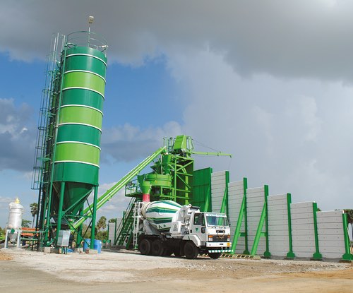
Ready mixed concrete:
If instead of being batched and mixed on site, concrete is delivered for placing from a central plant. It is referred to as ready-mixed or pre-mixed concrete. This type of concrete is used extensively abroad as it offers numerous advantages in comparison with other methods of manufacture:
Close quality control of batching which reduces the variability of the desired properties of hardened concrete.
Use on congested sites or in highway construction where there is little space for a mixing plant and aggregate stockpiles;
Use of agitator trucks to ensure care in transportation, thus prevention segregation and maintaining workability
Convenience when small quantities of concrete or intermittent placing is required.
There are two categories of ready-mixed concrete: central-mixed and transit mixed or truck mixed. In the first category, mixing is done in a central plant and then concrete is transported in an agitator truck. In the second category, the materials are batched at a central plant but are mixed in a truck.
Concrete Placing and Compaction of Concrete
The operation of placing and compaction are interdependent and are carried out simultaneously. They are most important for the purpose of ensuring the requirements of strength, impermeability and durability of hardened concrete in the actual structure. As for as placing is concerned, the main objective is to deposit the concrete as close as possible to its final position so that segregation is avoided and the concrete can be fully compacted. The aim of good concrete placing can be stated quite simply.
It is to get the concrete into position at a speed, and in a condition, that allow it to be compacted properly.
To achieve proper placing following rules should be kept in mind:
The concrete should be placed in uniform layers, not in large heaps or sloping layers.
The thickness of the layer should be compatible with the method of vibration so that entrapped air can be removed from the bottom of each layer.
The rate of placing and of compaction should be equal. If you proceed too slowly, the mix could stiffen so that it is no longer sufficiently workable. On no account should water ever be added to concrete that is setting. On the other hand, if you go too quickly, you might race ahead of the compacting gang, making it impossible for them to do their job properly.
Each layer should be fully compacted before placing the next one, and each subsequent layer should be placed whilst the underlying layer is still plastic so that monolithic construction is achieved
Collision between concrete and formwork or reinforcement should be avoided.
For deep sections, a long down pipe ensures accuracy of location of concrete and minimum segregation.
You must be able to see that the placing is proceeding correctly, so lighting should be available for large, deep sections, and thin walls and columns.
Compaction
Once the concrete has been placed, it is ready to be compacted. The purpose of compaction is to get rid of the air voids that are trapped in loose concrete.
Why is compaction of concrete necessary?
It is important to compact the concrete fully because:
Air voids reduce the strength of the concrete. For every 1% of entrapped air, the strength falls by somewhere between 5 and 7%. This means that concrete containing a mere 5% air voids due to incomplete compaction can lose as much as one third of its strength.
Air voids increase concrete's permeability. That in turn reduces its durability. If the concrete is not dense and impermeable, it will not be watertight. It will be less able to withstand aggressive iquids and its exposed surfaces will weather badly.
Moisture and air are more likely to penetrate to the reinforcement causing it to rust.
Air voids impair contact between the mix and reinforcement (and, indeed, any other embedded metals). The required bond will not be achieved and the reinforced member will not be as strong as it should be.
Air voids produce blemishes on struck surfaces. For instance, blowholes and honeycombing might occur.
Summing up, fully compacted concrete is dense, strong and durable; badly compacted concrete will be porous, weak and prone to rapid deterioration. Sooner or later it will have to be repaired or replaced. It pays, therefore, to do the job properly in the first place.
Stiff mixes contain far more air than workable ones. That is one of the reasons why a low-slump concrete requires more compactive effort than one with a higher slump - the compaction needs to continue for a longer time, or more equipment has to be used.
Even air-entrained concrete needs to be compacted to get rid of entrapped air voids. The difference between air voids and entrained air bubbles should be noted at this stage. The air bubbles that are entrained are relatively small and spherical in shape, increase the workability of the mix, reduce bleeding, and increase frost resistance. Entrapped air on the other hand tends to be irregular in shape and is detrimental to the strength of the mix. It is to remove this air that the concrete must be properly compacted. There is little danger that compaction will remove the minute air bubbles that have been deliberately entrained, since they are so stable.
Methods of Compaction of concrete
Vibration:
To compact concrete you apply energy to it so that the mix becomes more fluid. Air trapped in it can then rise to the top and escape. As a result, the concrete becomes consolidated, and you are left with a good dense material that will, after proper curing, develop its full strength and durability.
Vibration is the next and quickest method of supplying the energy. Manual techniques such as rodding are only suitable for smaller projects. Various types of vibrator are available for use on site.
Poker Vibrators
The poker, or immersion, vibrator is the most popular of the appliances used for compacting concrete. This is because it works directly in the concrete and can be moved around easily.
Sizes:
Pokers with diameters ranging from 25 to 75mm are readily available, and these are suitable for most reinforced concrete work. Larger pokers are available - with diameters up to 150mm - but these are for mass concrete in heavy civil engineering.
Radius of action:
When a poker vibrator is operating, it will be effective over a circle centred on the poker. The distance from the poker to the edge of the circle is known as the radius of action.
However, the actual effectiveness of any poker depends on the workability of the concrete and the characteristics of the vibrator itself. As a general rule, the bigger the poker and the higher its amplitude, the greater will be the radius of action. It is better to judge from your own observations, as work proceeds on site, the effective radius of the poker you are operating on the concrete you are compacting.
The length of time it takes for a poker vibrator to compact concrete fully depends on:
The workability of the concrete: the less workable the mix, the longer it must be vibrated.
The energy put in by the vibrator: bigger vibrators do the job faster.
The depth of the concrete: thick sections take longer.
There are various methods of curing. The adoption of a particular method will depend upon the nature of work and the climatic conditions. The following methods of curing of concrete are generally adopted.
Curing of Concrete
Shading concrete work
Covering concrete surfaces with hessian or gunny bags
Sprinkling of water
Ponding method
Membrane curing
Steam curing
1. Shading Of Concrete Work
The object of shading concrete work is to prevent the evaporation of water from the surface even before setting. This is adopted mainly in case of large concrete surfaces such as road slabs. This is essential in dry weather to protect the concrete from heat, direct sun rays and wind. It also protects the surface from rain. In cold weather shading helps in preserving the heat of hydration of cement thereby preventing freezing of concrete under mild frost conditions. Shading may be achieved by using canvas stretched on frames. This method has a limited application only.
2. Covering Concrete Surfaces With Hessian or Gunny Bags
This is a widely used method of curing, particularly for structural concrete. Thus exposed surface of concrete is prevented from drying out by covering it with hessian, canvas or empty cement bags. The covering over vertical and sloping surfaces should be secured properly. These are periodically wetted. The interval of wetting will depend upon the rate of evaporation of water. It should be ensured that the surface of concrete is not allowed to dry even for a short time during the curing period. Special arrangements for keeping the surface wet must be made at nights and on holidays.
3. Sprinkling of Water
Sprinkling of water continuously on the concrete surface provides an efficient curing. It is mostly used for curing floor slabs. The concrete should be allowed to set sufficiently before sprinkling is started. The spray can be obtained from a perforated plastic box. On small jobs sprinkling of water may be done by hand. Vertical and sloping surfaces can be kept continuously wet by sprinkling water on top surfaces and allowing it to run down between the forms and the concrete. For this method of curing the water requirement is higher.
4. Ponding Method
This is the best method of curing. It is suitable for curing horizontal surfaces such as floors, roof slabs, road and air field pavements. The horizontal top surfaces of beams can also be ponded. After placing the concrete, its exposed surface is first covered with moist hessian or canvas. After 24 hours, these covers are removed and small ponds of clay or sand are built across and along the pavements. The area is thus divided into a number of rectangles. The water is filled between the ponds. The filling of water in these ponds is done twice or thrice a day, depending upon the atmospheric conditions. Though this method is very efficient, the water requirement is very heavy. Ponds easily break and water flows out. After curing it is difficult to clean the clay.
5. Membrane Curing
The method of curing described above come under the category of moist curing. Another method of curing is to cover the wetted concrete surface by a layer of water proof material, which is kept in contact with the concrete surface of seven days. This method of curing is termed as membrane curing. A membrane will prevent the evaporation of water from the concrete. The membrane can be either in solid or liquid form. They are also known as sealing compounds. Bituminised water proof papers, wax emulsions, bitumen emulsions and plastic films are the common types of membrane used.
Whenever bitumen is applied over the surface for curing, it should be done only after 24 hours curing with gunny bags. The surface is allowed to dry out so that loose water is not visible and then the liquid asphalt sprayed throughout. The moisture in the concrete is thus preserved. It is quite enough for curing.
This method of curing does not need constant supervision. It is adopted with advantage at places where water is not available in sufficient quantity for wet curing. This method of curing is not efficient as compared with wet curing because rate of hydration is less. Moreover the strength of concrete cured by any membrane is less than the concrete which is moist cured. When membrane is damaged the curing is badly affected.
6. Steam Curing
Steam curing and hot water curing is sometimes adopted. With these methods of curing, the strength development of concrete is very rapid.
These methods can best be used in pre cast concrete work. In steam curing the temperature of steam should be restricted to a maximum of 750C as in the absence of proper humidity (about 90%) the concrete may dry too soon. In case of hot water curing, temperature may be raised to any limit, ay 1000C.
At this temperature, the development of strength is about 70% of 28 days strength after 4 to 5 hours. In both cases, the temperature should be fully controlled to avoid non-uniformity. The concrete should be prevented from rapid drying and cooling which would form cracks.
Steam curing can be used to advantage where early strength gain in concrete is important or where additional heat is required to accomplish hydration, as in cold-weather concreting. Source:- civilblog.org
ADVANTAGES:
It can be used in cold weather conditions for Rapid hardening of concrete
By this method high early age strength is achieved in concrete
Speedy construction can be achieved
Concrete curing time is less than the other methods of curing
It is mainly used for curing of precast members
DISADVANTAGES:
Steam curing method cannot will not be efficient for large surface.
Skilled labours are needed & special materials are required.
Initial cost of this curing method is high.
METHOD OF CURING:
There are two methods of steam curing (1) curing in live steam at atmospheric pressure (for enclosed cast in place structures and manufactured precast units) (2) curing in high pressure steam autoclaves (for small manufactured units) A steam curing cycle consists of:
An initial delay prior to steaming
A period for increasing temperature
A period for holding the maximum temperature constant
A period for decreasing temperature.
Source: wecivilengineers.blog.
Types of Joints in Concrete Constructions
Joints in concrete construction are construction, expansion, contraction and isolation joints. These joints are placed in concrete slabs and pavements at regular intervals to prevent development of cracks in concrete.
Types of Joints in Concrete Constructions
Types of joints in concrete constructions are:
Construction Joints
Expansion Joints
Contraction Joints
Isolation Joints
1. Construction Joints
Construction joints are placed in a concrete slab to define the extent of the individual placements, generally in conformity with a predetermined joint layout.
Construction joints must be designed in order to allow displacements between both sides of the slab but, at the same time, they have to transfer flexural stresses produced in the slab by external loads.
Construction joints must allow horizontal displacement right-angled to the joint surface that is normally caused by thermal and shrinkage movement. At the same time they must not allow vertical or rotational displacements. Fig.1 summarizes which displacement must be allowed or not allowed by a construction joint.
Fig.2: Types of Construction Joints in Concrete Structures
2. Expansion joints
The concrete is subjected to volume change due to many reasons. So we have to cater for this by way of joint to relieve the stress. Expansion is a function of length. The building longer than 45m are generally provided with one or more expansion joint. In india recommended c/c spacing is 30m. The joints are formed by providing a gap between the building parts. Also Read: Expansion Joint in Concrete – Types and Characteristics
3. Contraction Joints
A contraction joint is a sawed, formed, or tooled groove in a concrete slab that creates a weakened vertical plane. It regulates the location of the cracking caused by dimensional changes in the slab.
Unregulated cracks can grow and result in an unacceptably rough surface as well as water infiltration into the base, subbase and subgrade, which can enable other types of pavement distress.
Contraction joints are the most common type of joint in concrete pavements, thus the generic term “joint” generally refers to a contraction joint. Contraction joints are chiefly defined by their spacing and their method of load transfer. They are generally between 1/4 – 1/3 the depth of the slab and typically spaced every 3.1 – 15 m
4. Isolation Joints
Joints that isolate the slab from a wall, column or drainpipe
Isolation joints have one very simple purpose—they completely isolate the slab from something else. That something else can be a wall or a column or a drain pipe. Here are a few things to consider with isolation joints:
Walls and columns, which are on their own footings that are deeper than the slab subgrade, are not going to move the same way a slab does as it shrinks or expands from drying or temperature changes or as the subgrade compresses a little.
Even wooden columns should be isolated from the slab.
If slabs are connected to walls or columns or pipes, as they contract or settle there will be restraint, which usually cracks the slab—although it could also damage pipes (standpipes or floor drains).
Expansion joints are virtually never needed with interior slabs, because the concrete doesn’t expand that much—it never gets that hot.
Expansion joints in concrete pavement are also seldom needed, since the contraction joints open enough (from drying shrinkage) to account for temperature expansion. The exception might be where a pavement or parking lot are next to a bridge or building—then we simply use a slightly wider isolation joint (maybe ¾ inch instead of ½ inch).
Blowups, from expansion of concrete due to hot weather and sun, are more commonly caused by contraction joints that are not sealed and that then fill up with non-compressible materials (rocks, dirt). They can also be due to very long unjointed sections. Very long unjointed sections can expand enough from the hot sun to cause blow ups, but this is rare.
Isolation joints are formed by placing preformed joint material next to the column or wall or standpipe prior to pouring the slab. Isolation joint material is typically asphalt-impregnated fiberboard, although plastic, cork, rubber, and neoprene are also available.
Isolation joint material should go all the way through the slab, starting at the subbase, but should not extend above the top.
For a cleaner looking isolation joint, the top part of the preformed filler can be cut off and the space filled with elastomeric sealant. Some proprietary joints come with removable caps to form this sealant reservoir.
Joint materials range from inexpensive asphalt-impregnated fiberboard to cork to closed cell neoprene. Cork can expand and contract with the joint, does not extrude, and seals out water.
Scott Whitelam with APS Cork says that the required performance is what determines the choice of joint materials. How much motion is expect, exposure to salts or chemicals, and the value of the structure would all come into play—and of course the cost. Polyethylene foam isolation joint material comes in various colors. C2 Products
At columns, contraction joints should approach from all four directions ending at the isolation joint, which should have a circular or a diamond shaped configuration around the column. For an I-beam type steel column, a pinwheel configuration can work.
Always place the slab concrete first and do not install the isolation joint material and fill around the column until the column is carrying its full dead load.
Sealing of Various Types of Joint in Buildings
Protection systems of joints include the sealing of cracks, contraction (control) joints, expansion joints, and construction joints. Joint sealants in concrete minimize the intrusion of liquids, solids, or gases, and protect the concrete against damage.
Sealing of various types of joints is discussed below:
Sealing of Cracks in Buildings
Cracks are produced in concrete due to shrinkage, thermal changes, structural-related stresses, and long-term strain shortening. Before selecting a sealant, the reason for the cracking must be determined and moving cracks must be identified.
In some cases, structural bonding of a crack may be required, whereas in other situations, restraint across the crack is to be avoided.
Sealing of Contraction (control) Joints in Buildings
Contraction joints are intentional gaps / discontinuities provided to control crack locations to accommodate the contraction of concrete.
The necessary plane of weakness may be formed by reducing the concrete cross section by tooling or saw cutting a joint, usually within 24 h. It must be sealed in such a way that it must allow contraction to occur.
Sealing of Expansion (isolation) Joints in Buildings
Expansion joints are made by providing a space over the entire cross section between abutting structural units. These are used to prevent crushing and distortion of abutting concrete structural units due to the transmission of compressive forces.
These compressive forces may be developed by expansion, applied loads, or differential movements arising from the configuration of the structure or its settlement.
Sealing of Construction joints in Buildings
Construction joints are formed by interruptions in the placement of concrete or due to the positioning of precast units. Locations are usually predetermined so as to limit the work that can be done at one time to a convenient size.
They may be required to function later as expansion or contraction joints, or they may be required to be firmly bonded together so as to maintain complete structural integrity.
Construction joints may run horizontally or vertically depending on the placing sequence prescribed by the design of the structure.
Methods of Sealing Joints in Buildings
Methods to seal joints include injection techniques, routing and caulking, bonding, installing pre-molded seals, or installing appropriate surface protection systems (such as elastomeric membranes).
Concrete Mix Design Calculation for M20, M25, M30 Concrete with Procedure & Example
Home/Concrete Technology/Concrete Mix Design Calculation for M20, M25, M30 Concrete with Procedure & Example
Concrete mix design is the process of finding right proportions of cement, sand and aggregates for concrete to achieve target strength in structures. So, concrete mix design can be stated as Concrete Mix = Cement:Sand:Aggregates.
The concrete mix design involves various steps, calculations and laboratory testing to find right mix proportions. This process is usually adopted for structures which requires higher grades of concrete such as M25 and above and large construction projects where quantity of concrete consumption is huge..
Benefits of concrete mix design is that it provides the right proportions of materials, thus making the concrete construction economical in achieving required strength of structural members. As, the quantity of concrete required for large constructions are huge, economy in quantity of materials such as cement makes the project construction economical.
Concrete Mix design of M20, M25, M30 and higher grade of concrete can be calculated from example below.
Concrete Mix Design
Data Required for Concrete Mix Design
(i) Concrete Mix Design Stipulation
(a) Characteristic compressive strength required in the field at 28 days grade designation — M 25
(b) Nominal maximum size of aggregate — 20 mm
(c) Shape of CA — Angular
(d) Degree of workability required at site — 50-75 mm (slump)
(e) Degree of quality control available at site — As per IS:456
(f) Type of exposure the structure will be subjected to (as defined in IS: 456) — Mild
(g) Type of cement: PSC conforming IS:455
(h) Method of concrete placing: pump able concrete
(ii) Test data of material (to be determined in the laboratory)
(a) Specific gravity of cement — 3.15
(b) Specific gravity of FA — 2.64
(c) Specific gravity of CA — 2.84
(d) Aggregate are assumed to be in saturated surface dry condition.
(e) Fine aggregates confirm to Zone II of IS – 383
Procedure for Concrete Mix Design of M25 Concrete
Step 1 — Determination Of Target Strength
Himsworth constant for 5% risk factor is 1.65. In this case standard deviation is taken from IS:456 against M 20 is 4.0.
ftarget = fck + 1.65 x S
= 25 + 1.65 x 4.0 = 31.6 N/mm2
Where,
S = standard deviation in N/mm2 = 4 (as per table -1 of IS 10262- 2009)
Step 2 — Selection of water / cement ratio:-
From Table 5 of IS 456, (page no 20)
Maximum water-cement ratio for Mild exposure condition = 0.55
Based on experience, adopt water-cement ratio as 0.5.
0.5<0.55, hence OK.
Step 3 — Selection of Water Content
From Table 2 of IS 10262- 2009,
Maximum water content = 186 Kg (for Nominal maximum size of aggregate — 20 mm)
Table for Correction in water content
Parameters
Values as per Standard reference condition
Values as per Present Problem
Departure
Correction in Water Content
Slump
25-50 mm
50-75
25
(+3/25) x 25 = +3
Shape of Aggregate
Angular
Angular
Nil
–
Total
+3
Estimated water content = 186+ (3/100) x 186 = 191.6 kg /m3
Step 4 — Selection of Cement Content
Water-cement ratio = 0.5
Corrected water content = 191.6 kg /m3
Cement content =
From Table 5 of IS 456,
Minimum cement Content for mild exposure condition = 300 kg/m3
383.2 kg/m3 > 300 kg/m3, hence, OK.
This value is to be checked for durability requirement from IS: 456.
In the present example against mild exposure and for the case of reinforced concrete the minimum cement content is 300 kg/m3 which is less than 383.2 kg/m3. Hence cement content adopted = 383.2 kg/m3.
As per clause 8.2.4.2 of IS: 456
Maximum cement content = 450 kg/m3.
Step 5: Estimation of Coarse Aggregate proportion:-
From Table 3 of IS 10262- 2009,
For Nominal maximum size of aggregate = 20 mm,
Zone of fine aggregate = Zone II
And For w/c = 0.5
Volume of coarse aggregate per unit volume of total aggregate = 0.62
Table for correction in estimation of coarse aggregate proportion
Parameter
Values as per Standard reference condition
Values as per present problem
Departure
Correction in Coarse Aggregate proportion
Remarks
W/c
0.5
0.5
Nil
–
See Note 1
Workability
–
pump able concrete
–
-10%
See Note 2
Total
-10%
Note 1: For every ±0.05 change in w/c, the coarse aggregate proportion is to be changed by 0.01. If the w/c is less than 0.5 (standard value), volume of coarse aggregate is required to be increased to reduce the fine aggregate content. If the w/c is more than 0.5, volume of coarse aggregate is to be reduced to increase the fine aggregate content. If coarse aggregate is not angular, volume of coarse aggregate may be required to be increased suitably, based on experience. Note 2: For pump able concrete or congested reinforcement the coarse aggregate proportion may be reduced up to 10%.
Hence,
Volume of coarse aggregate per unit volume of total aggregate = 0.62 x 90% = 0.558
Volume of fine aggregate = 1 – 0.558 = 0.442
Step 6: Estimation of the mix ingredients
a) Volume of concrete = 1 m3
b) Volume of cement = (Mass of cement / Specific gravity of cement) x (1/100)
= (383.2/3.15) x (1/1000) = 0.122 m3
c) Volume of water = (Mass of water / Specific gravity of water) x (1/1000)
= (191.6/1) x (1/1000) = 0.1916 m3
d) Volume of total aggregates = a – (b + c ) = 1 – (0.122 + 0.1916) = 0.6864 m3
e) Mass of coarse aggregates = 0.6864 x 0.558 x 2.84 x 1000 = 1087.75 kg/m3
f) Mass of fine aggregates = 0.6864 x 0.442 x 2.64 x 1000 = 800.94 kg/m3
Concrete Mix proportions for Trial Mix 1
Cement = 383.2 kg/m3
Water = 191.6 kg/m3
Fine aggregates = 800.94 kg/m3
Coarse aggregate = 1087.75 kg/m3
W/c = 0.5
For trial -1 casting of concrete in lab, to check its properties.
It will satisfy durability & economy.
For casting trial -1, mass of ingredients required will be calculated for 4 no’s cube assuming 25% wastage.
Volume of concrete required for 4 cubes = 4 x (0.153 x1.25) = 0.016878 m3
Cement = (383.2 x 0.016878) kg/m3 = 6.47 kg
Water = (191.6 x 0.016878) kg/m3 =3.23 kg
Coarse aggregate = (1087.75 x 0.016878) kg/m3 =18.36 kg
Fine aggregates = (800.94 x 0.016878) kg/m3 = 13.52 kg
Step 7: Correction due to absorbing / moist aggregate:-
Since the aggregate is saturated surface dry condition hence no correction is required.
Step 8: Concrete Trial Mixes:-
Concrete Trial Mix 1:
The mix proportion as calculated in Step 6 forms trial mix1. With this proportion, concrete is manufactured and tested for fresh concrete properties requirement i.e. workability, bleeding and finishing qualities.
In this case,
Slump value = 25 mm
Compaction Factor = 0.844
So, from slump test we can say,
Mix is cohesive, workable and had a true slump of about 25 mm and it is free from segregation and bleeding.
Desired slump = 50-75 mm
So modifications are needed in trial mix 1 to arrive at the desired workability.
Concrete Trial Mix 2:
To increase the workability from 25 mm to 50-75 mm an increase in water content by +3% is to be made.
The corrected water content = 191.6 x 1.03 = 197.4 kg.
As mentioned earlier to adjust fresh concrete properties the water cement ratio will not be changed. Hence Cement Content = (197.4/0.5) = 394.8 kg/m3
Which also satisfies durability requirement.
Volume of all in aggregate = 1 – [{394.8/(3.15×1000)} + {197.4/(1 x 1000)}] = 0.6773 m3
Mass of coarse aggregate = 0.6773 x 0.558 x 2.84 x 1000 = 1073.33 kg/m3
Mass of fine aggregate = 0.6773 x 0.442 x 2.64 x 1000 = 790.3 kg/m3
Concrete Mix Proportions for Trial Mix 2
Cement = 384.8 kg/m3
Water = 197.4 kg/m3
Fine aggregate =790.3 kg/m3
Coarse aggregate = 1073.33 kg/m3
For casting trial -2, mass of ingredients required will be calculated for 4 no’s cube assuming 25% wastage.
Volume of concrete required for 4 cubes = 4 x (0.153 x1.25) = 0.016878 m3
Cement = (384.8 x 0.016878) kg/m3 = 6.66 kg
Water = (197.4 x 0.016878) kg/m3 =3.33 kg
Coarse aggregate = (1073.33 x 0.016878) kg/m3 =18.11 kg
Fine aggregates = (790.3 x 0.016878) kg/m3 = 13.34 kg
In this case,
Slump value = 60 mm
Compaction Factor = 0.852
So, from slump test we can say,
Mix is very cohesive, workable and had a true slump of about 60 mm.
It virtually flowed during vibration but did not exhibit any segregation and bleeding.
Desired slump = 50-75 mm
So , it has achieved desired workability by satisfying the requirement of 50-75 mm slump value .
Now , we need to go for trial mix-3 .
Concrete Trial Mix 3:
In case of trial mix 3 water cement ratio is varied by +10% keeping water content constant. In the present example water cement ratio is raised to 0.55 from 0.5.
An increase of 0.05 in the w/c will entail a reduction in the coarse aggregate fraction by 0.01.
Hence the coarse aggregate as percentage of total aggregate = 0.558 – 0.01 = 0.548
W/c = 0.55
Water content will be kept constant. Cement content = (197.4/0.55) = 358.9 kg/m3
Hence, volume of all in aggregate
= 1 – [{(358.9/(3.15 x 1000)} + (197.4/1000)] =0.688 m3
Mass of coarse aggregate = 0.688 x 0.548 x 2.84 x 1000 = 1070.75 kg/m3
Mass of fine aggregate = 0.688 x 0.452 x 2.64 x 1000 = 821 kg/m3
Concrete Mix Proportions of Trial Mix 3
Cement = 358.9 kg/m3
Water = 197.4 kg/m3
FA = 821 kg/m3
CA = 1070.75 kg/m3
For casting trial -3, mass of ingredients required will be calculated for 4 no’s cube assuming 25% wastage.
Volume of concrete required for 4 cubes = 4 x (0.153 x1.25) = 0.016878 m3
Cement = (358.9 x 0.016878) kg/m3 = 6.06 kg
Water = (197.4 x 0.016878) kg/m3 =3.33 kg
Coarse aggregate = (1070.75 x 0.016878) kg/m3 =18.07 kg
Fine aggregates = (821 x 0.016878) kg/m3 = 13.85 kg
In this case,
Slump value = 75 mm
Compaction Factor = 0.89
So, from slump test we can say,
Mix is stable, cohesive, and workable and had a true slump of about 75 mm.
Desired slump = 50-75 mm
So , it has achieved desired workability by satisfying the requirement of 50-75 mm slump value .
Now , we need to go for trial mix-4.
Concrete Trial Mix 4:
In this case water / cement ratio is decreased by 10% keeping water content constant.
W/c = 0.45
A reduction of 0.05 in w/c will entail and increase of coarse aggregate fraction by 0.01.
Coarse aggregate fraction = 0.558 +.01 =.568
W/c = 0.45 and water content = 197.4 kg/m3
Cement content = (197.4/0.45) = 438.7 kg/m3
Volume of all in aggregate
= 1 – [{438.7/(3.15 x 1000)} + (197.4/1000)] = 0.664 m3
Mass of coarse aggregate = 0.664 x 0.568 x 2.84 x 1000 = 1071.11 kg/m3
Mass of fine aggregate = 0.664 x 0.432 x 2.64 x 1000 = 757.28 kg/m3
Concrete Mix Proportions of Trial Mix 4
Cement = 438.7 kg/m3
Water = 197.4 kg/m3
FA = 757.28 kg/m3
CA = 1071.11 kg/m3
For casting trial -4, mass of ingredients required will be calculated for 4 no’s cube assuming 25% wastage.
Volume of concrete required for 4 cubes = 4 x (0.153 x1.25) = 0.016878 m3
Cement = (438.7 x 0.016878) kg/m3 = 7.4 kg
Water = (197.4 x 0.016878) kg/m3 =3.33 kg
Coarse aggregate = (1071.11 x 0.016878) kg/m3 =18.07 kg
Fine aggregates = (757.28 x 0.016878) kg/m3 = 12.78 kg
A local correction due to moisture condition of aggregate is again applied on this proportions. With corrected proportions three concrete cubes are cast and tested for 28 days compressive strength.
A summary of all the trial mixes is given in the following Table.
Recommended mix proportion of ingredients for grade of concrete M25:
From Compressive Strength vs. c/w graph for target strength 31.6 MPa we get,
W/c = 0.44
water content = 197.4 kg/m3
Cement content = (197.4/0.44) = 448.6 kg/m3
Volume of all in aggregate
= 1 – [{448.6/(3.15 x 1000)} + (197.4/1000)] = 0.660 m3
A reduction of 0.05 in w/c will entail and increase of coarse aggregate fraction by 0.01.
Coarse aggregate fraction = 0.558 +.01 =.568
Volume of fine aggregate = 1 – 0.568 = 0.432
Mass of coarse aggregate = 0.660 x 0.568 x 2.84 x 1000 = 1064.65 kg/m3
Mass of fine aggregate = 0.660 x 0.432 x 2.64 x 1000 = 752.71 kg/m3
===================================
Quantity of Cement, Sand & Aggregate used in 1m3 of Concrete | Concrete Mix Design
Concrete is a composite mixture which consists of Cement, Sand and Aggregate. Concrete mix design is the procedure for finding the right quantities of these materials to achieve the desired strength. Accurate concrete mix design makes concrete construction economical. Large constructions such as Bridges, dams requires huge amount of concrete, using the right quantity of constituents make the structure economical. In order to calculate or find the right amount of cement, sand and aggregate required in 1m3 of concrete; you need to know about different grades of concrete.
As per IS456:2000, Different grades of concrete are classified into M5, M7.5, M10, M15 etc., whereas M stands for Mix and the number behind M stands for Characteristic Compressive strength(fck) of the concrete in N/mm2 @28 days when checked with 15cm×15cm×15cm cube indirect compression test.
Concrete Mix design of M5, M7.5, M10, M15, M20, M25, M30 and higher grades of concrete is calculated as below:
The procedure for finding the different grades of concrete mixes are same. The below mentioned method can be applied to any grade of concrete by changing the values. To make ease in understanding we are finding the Concrete mix design of M20 grade concrete.
The Concrete mix ratio for M20 grade of concrete is 1:1.5:3 that mean 1 part of cement, 1.5 part of sand (fine aggregate) and 3 parts of aggregate (crushed stone) in volume and then batched for mixing. To know the Concrete Mix Design follow below:-
Mix Design (M) = Cement: Sand :Aggregate
As per BS 8500-2 British/European standards The grade of concrete is denoted as C10, C15, C20,C25, etc., ‘C’ which means ‘ConcreteStrength class’ and number behind C refers to characteristic Compressive strength of Concrete in N/mm2 @ 28 days when tested with the 15cm dia & 30cm height cylinder in direct compression test
The grade of concrete is also denoted as C16/20, C20/25, C25/30, etc., which means Concrete Strength Class (C) the number behind C refers to Compressive strength of Concrete in N/mm2 when tested with Cylinder / Cube.
Remember : 1MPA = N/mm2
Different grades of concrete :
Different grades of concrete has different Concrete Mix proportions which means different concrete mix ratios. As Per IS456:2000, the Concrete mix design has the following concrete mix proportions :-
Type of Concrete
Concrete Grade
Mix Ratio
Characteristic
Compressive strength of
Concrete
@28Days in N/mm2
Ordinary concrete
M5
1:5:10
5 N/mm2
M7.5
1:4:8
7.5 N/mm2
M10
1:3:6
10 N/mm2
M15
1:2:4
15 N/mm2
M20
1:1.5:3
20 N/mm2
Standard Concrete
M25
1:1:2
25 N/mm2
M30
Design Mix
30 N/mm2
M35
Design Mix
35 N/mm2
M40
Design Mix
40 N/mm2
M45
Design Mix
45 N/mm2
M50
Design Mix
50 N/mm2
High Strength
Concrete
M55
Design Mix
55 N/mm2
M60
Design Mix
60 N/mm2
M65
Design Mix
65 N/mm2
M70
Design Mix
70 N/mm2
Different types of Concrete mixes:
Concrete Mixes are primarily divided into the two different types :
Nominal Mix:
Nominal Mix is generally adopted for small scale constructions. In this type of mix, the mix ratios and concrete constituent proportions are prefixed and specified. Eg: M20(1:1.5:3); the quantity of cement, sand and aggregate is batched in volume as per the fixed ratio 1:1.5:3. From the above table till M25 grade, the concrete proportions are called as Nominal mix concrete.
Design Mix:
Design mix concrete is adopted for high rise constructions. In this type of mix, the mix ratios are decided by an Engineer after analysing the properties of individual ingredients of concrete. Like, cement is tested for Fineness modulus and Specific gravity of cement in the lab while deciding the Design mix ratio. There is No Pre-fixed ratio, and ingredients are are batched in weight. From the above table, concrete grades more than M25 falls in Design mix.
In Simple, Design Mix refers to the ratios which are decided by the designer.
Calculation of Quantities of Cement, Sand and Aggregate in 1m3 of concrete:-
To calculate the individual quantities of cement, sand and aggregate required for 1m3 assume a nominal mix grade of concrete such as M20. You can use same method to calculate any grade of concrete.
Concrete Mix Design for M20 Grade Concrete:-
Now let us consider M20 grade concrete;
As per IS456:2000, M20 Grade concrete proportion is = 1 : 1.5 : 3
We have to add all the volume to know the total volume = 1 + 1.5 + 3 = 5.5
As we know that during concreting when we place wet concrete, it gets harden after certain standard time. Considering the same it had be decided upon by Civil design Engineers to take a factor of safety ranging from 1.54 to 1.57 to counter that shrinkage.
i.e volume of dry Concrete = 1.54 to 1.57 times Volume of wet concrete
I am Assuming 1.57 as factor of safety
So total volume of concrete required is 1.57 m3
Calculation of Volume of Cement in 1m3 of Concrete:-
To calculate the Quantity of Cement in Concrete the following formula is used.
Volume of Cement
= Cement⁄Cement+Sand+Aggregate x 1.57
For 1m3 of Concrete = 403.2Kgs of Cement is required.
No. of Cement Bags required for 1m3 of Concrete = 403/50 = 8.06 ~ 8 bags
Hence we require 8 bags of cement for 1m3 of concrete.
Calculation of Volume of Sand (Fine Aggregate) in 1m3 of Concrete:-
The following steps are followed to find the quantity of sand in 1m3 of concrete.
Volume of Sand
= Sand⁄Cement+Sand+Aggregate x 1.57
Sand usually consists of moisture content. It increases the volume of sand (bulking of sand).
For accurate calculation use dry sand or include the effect of bulking as mentioned above in calculation.
Hence we require 672kg of sand for 1 cu.m of concrete.
Calculation of Volume of Coarse Aggregate in 1m3 of Concrete:-
The following formula is used to find the quantity of coarse aggregate in 1m3 of concrete.
Volume of Aggregate
= Aggregate⁄Cement+Sand+Aggregate x 1.57
Density of aggregate may go higher if void spaces decreases. 5mm aggregate has more density when compared with 20mm size of aggregate
Hence We require 1326Kg of 20mm aggregate for 1m3 of Concrete.
Amount of Water Required for 1m3 of Concrete:-
For making concrete, required amount of water is added. Water quantity is depends upon the climatic factors and workability required. We generally maintain 0.35-0.50 of water cement ratio. Remember, above values may change according to the moisture content present in sand and aggregate.
Cement Required for 1m3 of Concrete = 400Kgs
Assume W/C ratio = 0.50 (50% of cement)
Water required for 1m3 of Concrete. = 400 x 0.50
Amount of Water Required for 1m3 of Concrete = 200kgs = 200 litres
Hence 200 Litres of Water is required for 1m3 of M20 Concrete Summary: – 8 bags of cement required for 1 cu.m of M20 grade concrete. 672 kg of Sand required for 1 cu.m of M20 grade concrete. 1326 kg of 20mm Aggregate is required for 1 cu.m of M20 grade concrete. 200 litres of water is required for 1 cu.m of M20 grade concrete
Table for Quantity of Cement, Sand, - ----------
------------------------------------
Factors Affecting Concrete Mix Design Strength
The mixing of concrete constituent materials i.e. cement, water, aggregates and admixtures in specified proportions will produce a concrete of adequate strength. The mix design strength developed for a given type of cement is dependent on the following factors:
Water/Cement Ratio
Cement Content
Relative proportion of fine and coarse aggregates
Admixture
Factors Affecting Concrete Mix Design Strength
The above stated design strength variable factors are explained below based on different theories and specifications.
1. Water/cement ratio
Water to cement ratio (W/C ratio) is the single most important factor governing the strength and durability of concrete. Strength of concrete depends upon W/C ratio rather than the cement content.
Abram’s law states that “higher the water/cement ratio, lower is the strength of concrete.” As a thumb rule every 1% increase in quantity of water added, reduces the strength of concrete by 5%.
A water/cement ratio of only 0.38 is required for complete hydration of cement. (Although this is the theoretical limit, water cement ratio lower than 0.38 will also increase the strength, since all the cement that is added, does not hydrate) Water added for workability over and above this water/cement ratio of 0.38, evaporates leaving cavities in the concrete. These cavities are in the form of thin capillaries. They reduce the strength and durability of concrete. Hence, it is very important to control the water/cement ratio on site.
Every extra liter of water will approx. reduce the strength of concrete by 2 to 3 N/mm2and increase the workability by 25 mm. As stated earlier, the water/cement ratio strongly influences the permeability of concrete and durability of concrete. Revised IS 456-2000 has restricted the maximum water/cement ratios for durability considerations by clause 8.2.4.1, table 5.
2. Cement content
Cement is the core material in concrete, which acts as a binding agent and imparts strength to the concrete. From durability considerations cement content should not be reduced below 300Kg/m3 for RCC.
As per IS 456 –2000 , higher cement contents is required for severe conditions of exposure of weathering agents to the concrete. It is not necessary that higher cement content would result in higher strength. In fact, latest findings show that for the same water/cement ratio, a leaner mix will give better strength.
However, this does not mean that we can achieve higher grades of concrete by just lowering the water/cement ratio. This is because lower water/cement ratios will mean lower water contents and result in lower workability. In fact, for achieving a given workability, a certain quantity of water will be required. If lower water/cement ratio is to be achieved without disturbing the workability, cement content will have to be increased.
Higher cement content helps us in getting the desired workability at a lower water/cement ratio. In most of the mix design methods, the water contents to achieve different workability levels are given in form of empirical relations.
Water/cement ratios required to achieve target mean strengths are interpolated from graphs given in IS 10262 Clause 3.1 and 3.2 fig 2. The cement content is found as follows:
Thus, we see that higher the workability of concrete, greater is cement content required and vice versa. Also, greater the water/cement ratio, lower is the cement content required and vice versa.
3. Relative Proportion of Fine & Coarse Aggregates
Aggregates are of two types as below:
Coarse aggregate (Metal): These are particles retained on standard IS 4.75mm sieve.
Fine aggregate (Sand): These are particles passing standard IS 4.75mm sieve.
When comparing coarse and fine aggregates, the coarse aggregate tends to occupy one third of the volume of the concrete. This means that a change in coarse aggregate would bring a change in the strength of the concrete.
Proportion of fine aggregates to coarse aggregate depends on following:
Fineness of sand: Generally, when the sand is fine, smaller proportion of it is enough to get a cohesive mix; while coarser the sand, greater has to be its proportion with respect to coarse aggregate.
Size& shape of coarse aggregates: Greater the size of coarse aggregate lesser is the surface area and lesser is the proportion of fine aggregate required and vice versa. Flaky aggregates have more surface area and require greater proportion of fine aggregates to get cohesive mix. Similarly, rounded aggregate has lesser surface area and require lesser proportion of fine aggregate to get a cohesive mix.
Cement content: Leaner mixes require more proportion of fine aggregates than richer mixes. This is because cement particles also contribute to the fines in concrete.
The grading of the aggregates in the concrete mix design is an important factor that would determine the amount of paste that is required for the concrete. If the amount of voids present is high, more cement will be required to fill it. The use of well graded aggregates will help to reduce this void content to some extent. This will demand for less paste.
4. Admixtures
A variety of admixtures are available in the market that is used to serve various purposes. The admixtures are used in the concrete mix design when they have to solve certain concerns. Some of these concerns are:
To decrease the cost of construction
To achieve certain properties effectively
To maintain the concrete quality throughout the process of mixing, transporting, placing and compacting
Among various admixtures available, the strength gain in concrete is achieved through the use of water reducing admixtures. As mentioned above, the water cement ratio cannot be decreased to a certain limit as it would affect the workability of the mix. This property can be achieved by the use of water reducing admixtures that would give both a cement rich mix and a workable mix without the use of excess water.
A good workable mix can be obtained only by adding 45 to 55% water by the weight of cement. This will result the water to remain in excess even after the completion of hydration. These excess water in the pores get evaporated and create voids. These voids are the primary reason behind the development of failure cracks which weakens the concrete. Hence decrease in voids by the use of less amount of water can be achieved through water reducing admixtures.
Mentioned below are some of the admixtures and their respective roles in the concrete mix design strength.
Table.1: Strength Property Gained by Different Admixture
Sl. No
Type of Admixture
Property Gained
1
High Range Water Reducers
Decrease the water and cement content hence lower the water cement ratio.
Early Strength Gain
Results in High strength Concrete
Reduce Chloride-ion penetration
2
Accelerating Admixtures
Increase Rate of Hydration- Initial Setting of the concrete
Early Age Strength Development
3
Water-Reducing Admixtures
Reduce water-cement ratio
Reduce cement content
Increase slump
------------------------------------------------------------------------ DIFFERENT METHOD OF MIX DESIGN OF CONCRETE PROCEDURE
MIX DESIGN
The procedure of selecting suitable ingredients and determine their relative proportions with the objectives of producing concrete of having certain minimum workability, strength and durability as economically as possible is known as mix design.
The various factors to be consider in specifying a concrete mix are :
Water cement ratio
Cement content gradation
Consistency of the fresh concrete
METHOD OF MIX DESIGN OF CONCRETE
Trial and error method
American concrete institute method.
Maximum density of aggregate method
Surface area of aggregate method
Fineness modulus method
Void cement ratio and mortar void ratio method
Road note method
TRIAL AND ERROR METHOD
Based on the relationship between the w/c ratio and compressive strength. the design of the mix can be made by following steps :
Select the water cement ratio to suit the requirement of the strength and durability.
With this water cement ratio prepare trial batches with different aggregate cement ratios. From this it is possible to determine the optimum proportion and amount of the aggregate that will produce a workable mix with a minimum of the pastes content for determining the fine aggregate. It can be said that in the correct amount of sand is the minimum which will produce enough mortar to fill the spaces between the coarse aggregate and slightly more for workability. Understanding creates hardness and over standing results in less yield. with judgement and experience one ma arrive at the proportions of fine and coarse aggregate.
Having fixed water cement ratio, aggregate cement ratio and the amount of fine aggregate in the total aggregate content, block of concrete can be prepared in the laboratory following the standard procedure. After the required period of curing the blocks can be tested for its compressive strength.
mix can be slightly adjusted, if necessary, by changing the w/c ratio or the aggregate cement ratio suit the actual requirement of the job.
In the trial and error method, due consideration has to be given for the moisture content of the aggregates.
AMERICAN CONCRETE INSTITUTE METHOD (ACI METHOD)
This is the common method for design of concrete mix. the following are the steps :
Select the water cement ratio to concrete of the required durability and strength. if water cement ratio is determine by both methods and then the lower of the two values obtained should be used.
Select the lowest slump from ASI table.
The maximum size of aggregate recommended for the types of construction is selected by ASI table. Within the limit shown, the larges permissible maximum size should be employed, except as dictated by available and economy.
Estimate from the test data, minimum proportion of fine to coarse aggregate and the lowest water content as that will give the required degree of workability.
The cement content is computed by dividing the total water content by the w/c ratio.
The bulk volume of the dry rodded coarse aggregate per unit volume of concrete for the particular maximum size of the aggregate and fineness modulus of the sand is determine.
Determine the trial mix proportions and make adjustment if necessary for the materials and water cement ratio.
MAXIMUM DENSITY OF AGGREGATE METHOD
It is also known as fullar and thomson method of concrete mix design, the basis for proportioning the aggregate is maximum density. For this method, the studies made by fullar and thomson, in which sieve analyses were made to obtain proportions aggregate giving maximum density of concrete, were used. But this method is not in much uses now.
Maximum density of this combined aggregate can be determine is follow. In a of known volume certain proportions of any rodded mixed aggregate are filled in. Sand is taken as 0, 20, 30, 40, 50, 60 and 100% of the total weight. After each filling of the mould with the combined aggregates, weight is taken. A curve is then drawn showing the percentage of sand in the aggregate by weight v/s unit weight of the total aggregate in the mould, from this percentage of sand at which unit weight is maximum can be determined.
Architectural concrete construction needs special care in the selection of materials, forming, placing, and finishing in order to achieve the designated architectural appearance. Architectural concrete stays permanently exposed to view on surfaces of completed structures making important for ...
Blended cement can be defined as uniform mix of ordinary Portland cement (OPC) and blending materials such as silica fumes, fly ash, limestone and slag to enhance its properties for different uses. Blended cement can improve workability, strength, durability and ...
Contraction joints in concrete are provided at regular interval to from a weak plane, so that cracks are formed at the joints but not in undesired places. Contraction joints are provided in concrete pavements, slabs, walls, floors, dams, canal linings, ...
Dry mix process and wet mix process are the two methods of shotcrete construction which are based on the time at which the water is added to the mortar or concrete mix. in Dry mix process, water is added at ...
One of the key differences between the self-compacting concrete (SCC) and normal cement concrete (NCC) is the flowability property of SCC by it's on weight. Most of the differences shown by SCC is due to this variation of flowability from ...
What is a Reactive Powder Concrete? Reactive powder concrete (RPC) is the ultra-high strength concrete prepared by replacing the ordinary aggregate of normal concrete with quartz powder, silica fume, steel fibers etc. RPC not only has high strength but also has ...
Sulphate Resisting Cement is a type of Portland Cement in which the amount of tricalcium aluminate (C3A) is restricted to lower than 5% and (2C 3A +C4AF) lower than 25%, which reduces the formation of sulphate salts. The reduction of sulphate ...
Portland Pozzolana cement is integrated cement which is formed by synthesising OPC cement with pozzolanic materials in a certain proportion. It is commonly known as PPC cement. In this article we discuss about the properties, manufacture, characteristics, advantages and disadvantages ...
Cracks in concrete buildings have several causes. They may show total extent of damage or problems of greater magnitude. They may represent critical structural distress, lack of durability, or they might influence appearance only. The importance of cracks dependent on the nature of cracking and type of structure.
Causes of different types of building cracks and their remedies will be discussed below.
Causes of Cracks in Concrete Buildings
The principal causes of cracks in a building are as follows:
Permeability of concrete
Thermal movement
Creep movement
Corrosion of reinforcement
Moisture movement
Poor construction practices
Improper structural design and specifications
Poor maintenance
Movement due to chemical reactions
other factors
1. Permeability of concrete
As deterioration process in concrete begins with penetration of various aggressive agents. it dictates the ability of concrete to withstand weathering action, chemical attack, or any process of deterioration. Therefore, low permeability is a key factor to concrete durability.
There are number of factors that controls concrete permeability like water-cement ratio, use of admixtures, curing, air voids due to deficient compaction, micro-cracks due to loading, cyclic exposure to thermal variations, and age of concrete.
The first three are allied to the concrete strength as well. The permeability of cement paste is a function of water-cement ratio given good quality materials, satisfactory proportioning and good construction practice; the permeability of the concrete is a direct function of the porosity and interconnection of pores of the cement paste.
Remedial measures
The above discussion suggests suitable measure to decrease concrete permeability and hence cracks.
2. Thermal movement
Thermal movement is one of the most potent causes of cracking in buildings. All materials more or less expand on heating and contract on cooling.
Ambient temperature changes and loss of heat of hydration in portion of structure at different rate lead to temperature variations and subsequent thermal movement.
The thermal movement in a component depends on a number of factors such as temperature variations, dimensions, coefficient of thermal expansion and some other physical properties of materials.
Thermal variations in the internal walls and intermediate floors are not much and thus do not cause cracking.
It is mainly the external walls especially thin walls exposed to direct solar radiation and the roof which are subject to substantial thermal variation that are liable to cracking.
Fig.1: Concrete cracking due to temperature variations
Fig.2: Cracking due to thermal movement
Remedial Measures
Joints shall be considered during the design and constructed properly. For example, expansion joints, construction joints, control joints, and slip joints.
Fig.3: Joints to prevent cracking due to thermal movement
3. Creep Movement
Gradual and slow time dependent deformation of concrete structure under sustained loads is known as creep. It may generate excessive stress and lead to the crack development.
Creep increases with increase in water and cement content, water cement ratio and temperature.
Added to that, admixtures and pozzolans will increase creep. The increase of temperature in steel bars will increase creep as well.
However, it decreases with increase in humidity of surrounding atmosphere and age of material at the time of loading.
Fig.4:concrete building cracks due to creep movement
Remedial measures
Use minimum possible quantity of water.
Employ large coarse aggregate.
Provide compression reinforcement if possible
Avoid formwork removal at early ages.
Cure concrete properly.
assign proper cross section for the concrete element.
4. Corrosion of Reinforcement
Reinforcement corrosion will produce iron oxide and hydroxide on steel bar surface, consequently its volume increases.
This increase in volume causes high radial bursting stresses around reinforcing bars and result in local radial cracks. These splitting cracks results in the formation of longitudinal cracks parallel to the bar.
Reinforcement corrosion will occur unless it is protected properly. Steel reinforcement can be protected by providing adequate impervious concrete cover. This will prevent the ingression of moisture and other aggressive elements.
Steel corrosion will also not occur as long as concrete surrounding it is alkaline in nature having a high pH value.
Fig.5: Cracking due to corrosion of reinforcement
Fig.6:Concrete cracking due corrosion of reinforcement
Remedial Measures
Use low permeable concrete
Provide adequate cover thickness
Make sure concrete-steel bond is as good as possible. This is because concrete alone is not capable of resisting tensile forces to which it is often subjected. Otherwise, concrete may crack and allow harmful substance materials to attack steel bars.
5. Moisture Movement
Most of the building materials with pores in their structure in the form of inter-molecular space expand on absorbing moisture and shrink on drying.
These movements are cyclic in nature and are caused by increase or decrease in inter pore pressure with moisture changes.
Shrinkage can be of plastic or dry. Factors that cause cement or mortar to experience shrinkage include excessive water, and cement quantity; rich cement mixtures suffer greater shrinkage.
Fig.7:Crack above window due shrinkage
Fig.8:concrete cracking due to moisture movement
Remedial measures
Provide movement joints
Use minimum possible quantity of water for mixing cement concrete or cement mortar
There are broad variety of construction practices that lead to concrete cracking. Normally, improper construction practices are due to ignorance, carelessness, greed or negligence.
main causes for poor construction practices:
Improper selection of materials.
Selection of poor quality cheap materials.
Inadequate and improper proportioning of mix constituents of concrete, mortar etc.
Inadequate control on various steps of concrete production such as batching, mixing, transporting, placing, finishing and curing
Construction overloads induced during construction can frequently be more serious than those imposed during service.
Inadequate quality control and supervision causing large voids (honey combs) and cracks resulting in leakages and ultimately causing faster deterioration of concrete.
Improper construction joints between subsequent concrete pours or between concrete framework and masonry.
Addition of excess water in concrete and mortar mixes.
Lastly, poor quality of plumbing and sanitation materials and practices.
Fig.9:Concrete building cracking due to poor construction practice; water added to fresh concrete
Remedial measure
monitoring construction process properly.
Utilize good quality materials at the time of construction.
7. Improper Structural Design and Specifications
Several problems can occur due to incorrect structural design, detailing, and specifications.
Errors that may occur at this stage include inadequate thickness, insufficient reinforcement, incorrect geometry, improper utilization of materials, and incorrect detailing.
Problems encountered due to those errors include cracking due to insufficient reinforcement, excessive differential movement due to improper foundation design, increased concentration of stresses as a result of poorly design re-entrant etc.…
Additionally, it is of crucial that the designer consider the environmental conditions existing around the building site.
Fig.10:Major structural crack in beam due to poor detailing practice
Remedial measures
Architects, Structural Consultants and Specifiers shall consider the following measure to avoid cracking and subsequent deterioration of structures:
Proper specification for concrete materials and concrete.
Proper specifications to take care of environmental as well as sub – soil conditions.
Constructible and adequate structural design.
Proper quality and thickness of concrete cover around the reinforcement steel.
Planning proper reinforcement layout and detailing the same in slender structures to facilitate proper placing of concrete without segregation.
Selection of proper agency to construct their designs.
8. Poor Maintenance
A structure needs to be maintained after a lapse of certain period from its construction completion.
Some structures may need a very early look into their deterioration problems, while others can sustain themselves very well for many years depending on the quality of design and construction.
Moreover, regular external painting of the building to some extent helps in protecting the building against moisture and other chemical attacks.
Waterproofing and protective coating on reinforcement steel or concrete are all second line of defense and the success of their protection will greatly depend on the quality of concrete.
Leakages should be attended to at the earliest possible before corrosion of steel inside concrete starts and spalling of concrete takes place.
Furthermore, Spalled concrete will lose its strength and stiffness. besides, The rate of corrosion increases because the rusted steel is entirely exposed to aggressive environment.
Finally, it is not only essential to repair the deteriorated concrete but it is equally important to prevent the moisture and aggressive chemicals to enter concrete and prevent further deterioration.
Fig.11:Leakage from roof slab
9. Movement due to Chemical Reactions
The concrete may crack as a result of expansive reactions between aggregate, which contains active silica, and alkaline derived from cement hydration.
The alkali silica reaction results in the formation of swelling gel. This tends to draw water from other portions of concrete. Consequently, local expansion occur and results in cracks in the structure.
Fig.12:Cracking due to alkali-silica reactions
Remedial measures
Use low alkali cement
Employ pozzolana
Select proper aggregates.
10. Others factors
Brutal decoration, free to remove the load-bearing walls or holes, causing cracks.
Fires caused by accidents, fires, mild earthquakes, etc.
WHAT CAUSES CRACKS IN CONCRETE AND HOW TO PREVENT IT?
Cracks in concrete are caused due to following factors.
One of the main causes of cracks in concrete is the cooling and contraction due to setting of concrete. Volume change and stresses due to shrinkage are independent of any external load or stress applied.
Cracks may develop in a smaller section attached to a large section due to differential expansion and contraction. Therefore a joint should be provided at the change of section. There is more possibility of cracking of fixed members than those which are free to expand and contract as simply supported beams.
Repeated expansion and contraction or alternate wetting and drying which may result in gradual disintegration of poor concrete.
Rapid drying due to hot weather and high speed winds or absorption of water from the concrete by wooden forms also a cause of cracking in concrete. Therefore the form work on which fresh concrete is placed must be damped, or it should be waterproof so that it does not absorb water from fresh concrete.
Loose form work can also lead to cracks in concrete. so form work should be of adequate strength to bear the pressure of the wet concrete without swelling, spreading or any movement.
Concentration of tensile reinforcement at square openings or re-entrant angles (as in corners of door and window openings) causes cracks. This can be avoided by suitably placing reinforcements having adequate covering. Sufficient thickness of concrete should be given at the points where bars are bent up and anchored.
Minute cracks on the tension side of a reinforced concrete member are unavoidable due to poor tensile strength of concrete as compared to steel and which must crack when steel reinforcement taken its load. Those cracks, however, should be fine enough for moisture penetration to prevent corrosion of the reinforcement.
Hair cracks are the result of unequal shrinkage of the surface concrete and the mass behind it. Delayed finishing and final floating of concrete can avoid these cracks up t o a certain limit.
Surface cracks are also caused by surface dressing with a mortar having too rich in cement. Too much water, insufficient curing, or from over trowelling. One method of avoiding such hair cracks is to remove the surface skin of the concrete by brushing it with a stiff brush soon after setting.
Contraction of concrete is more harmful than expansion as it sets up tensile stresses in the structure, particularly those with a large surface area and thus form cracks. Such contracting cracks may be prevented by inserting reinforcement near the surface. Closely spaced reinforcement of small diameter and near the surface is more effective than large diameter bars further apart from the surface.
Which Are Various Reasons of Cracks in Buildings?
Cracks can occur due to chemical reactions in construction materials, changes in temperature and climate, foundation movements and settling of buildings, environmental stresses like nearby trains, earth quakes etc. Faulty design, bad quality materials, wrong method of construction, weather effects and lots of wear and tear can create cracks in walls, floors and ceilings. Here are given various reasons of cracks and their prevention techniques.
To know “Repair of Cracks” in buildings, click at the link below.
When the walls are unevenly loaded, due to variation in stresses in different parts of wall the cracks are formed in walls. When two materials having wide different elastic properties are built together under the effect of load, different shear stresses in these materials create cracks at the junction. Dead and live loads cause elastic deformation in structural components of a building.
Prevention
Create slip joints under the support of RCC slab on walls. Masonry work on RCC slabs and beams should not be started before drying RCC slab and beam. Provide horizontal movement joints between the top of brick panel and RCC beam/slab.
Thermal Movement
All materials expand on heat and contract on cool. Thermal movement in components of structure creates cracks due to tensile of shear stresses. It is one of the most potent causes of cracking in buildings and needs attention.
Prevention
Construct joints such as construction joints, expansion joints, control joints and slip joints. The joints should be planned at the time of design and be constructed carefully.
Chemical Reaction
Chemical reactions in building materials increase their volume and internal stress causes cracks. The components of structure also weaken due to chemical reactions. Some common instances of chemical reactions are following.
Sulphate attack on cement products
Carbonation in cement based materials
Corrosion of reinforcement in concrete
Alkali aggregate reaction
Prevention
Use dense and good quality concrete i.e. richer mix of cement concrete 1:1.5:3 to prevent cracks. Repair corrosive cement concrete surface by ‘guniting’/ injecting technique after removing all loose and damaged concrete and cleaning reinforcement from all rust also.
Shrinkage
Most building materials expend when they absorb moisture from atmosphere and shrink when they are dry. Cement made materials shrink due to drying up of the moisture used in their construction. The factors causing shrinkage in cement concrete and cement mortar and their preventions are following.
Excessive Water
The quantity of water used in the mortar mix can cause shrinkage. Vibrated concrete has less quantity of water and lesser shrinkage than manually compacted concrete.
Prevention
Use minimum quantity of water required for mixing cement concrete or cements mortar according to water cement ratio. Never allow cement concrete work without mechanical mix and vibrator.
Quantity of Cement
As a general rule, the richer the mix is, the greater the shrinkage/drying will be.
Prevention
Do not use excessive cement in the mortar mix.
Un-graded Aggregate
Aggregate can cause shrinkage also. If un-graded and fine material/aggregate is used in cement concrete and cement mortar which requires more water and can cause greater shrinkage.
Prevention
Use largest possible aggregate and ensure good grading of materials. The use of water according to required workability has less shrinkage because of reduction in the porosity of hardened concrete.
Curing
After laying cement concrete mix, the hardening of cement takes place, causes reduction in moisture and creates shrinkage. This causes cracks in concrete work.
Prevention
Proper curing should be started as soon as initial setting has taken place and be continued for at least seven to ten days. When hardening of concrete takes place under moist environment, the shrinkage due to drying is comparatively less.
Excessive Fine materials
Fine materials take more surface area and require more water for mix. The use of excessive fine materials i.e. silts; clay and dust in aggregate create more shrinkage.
Prevention
Do not use fine materials containing silt, clay and dust. Use coarse sand/fine aggregate in cement concrete and cement mortar mix which has silt and clay less than 4%. Use coarse aggregate and fine aggregate after washing to reduce silt contents.
Foundation Movement and Settlement of Soil
Shear cracks occur in buildings when there is large differential settlement of foundation due to any of following causes.
Unequal bearing pressure under different parts of the structure
Bearing pressure being in excess of safe bearing strength of the soil
Low factor of safety in the design of foundations
Local variation in the nature of supporting soil
Prevention
The design of foundation must be based on sound engineering principles and good practice.
Earth Quake
Crack may occur due to sudden shift in lower layer of the earth. The voids in the earth might have suddenly collapsed and be filled with soil from the above. Many geological events can trigger earth movements but is continuous movement. This results in cracks.
Prevention
Construct the foundation of buildings on firm ground while doing construction. Tie up the building with connecting beams at foundation level, door level and roof level.
Vegetation
The roots of trees located in the vicinity of a wall can create cracks in walls due to growth of roots under foundation. The cracks occur in clay soil due to moisture contained by roots.
Prevention
Do not let trees grow too close to the buildings, compound walls etc. Remove any saplings of trees as soon as possible if they start growing in or near of walls etc.
There are several methods of concrete crack repair such as epoxy injection, routing and sealing, grouting, stitching, drilling and plugging, gravity filling of cracks in concrete.
Details of these methods for the selection of suitable methods for different types of cracks in concrete are discussed.
How to Select Suitable Method of Concrete Crack Repair?
Suitable method for repair of cracks in concrete can be selected based on evaluation of the crack in structure for its causes. Once the cause is known and type of crack is established, then suitable method can be selected.
For example, if the cracking was primarily due to drying shrinkage, then it is likely that after a period of time the cracks will stabilize. On the other hand, if the cracks are due to a continuing foundation settlement, repair will be of no use until the settlement problem is corrected.
Epoxy injection method is used for cracks as narrow as 0.002 inch (0.05 mm). The technique generally consists of establishing entry and venting ports at close intervals along the cracks, sealing the crack on exposed surfaces, and injecting the epoxy under pressure.
Epoxy injection has been successfully used in the repair of cracks in buildings, bridges, dams, and other types of concrete structures (ACI 503R). However, unless the cause of the cracking has been corrected, it will probably recur near the original crack. If the cause of the cracks cannot be removed, then two options are available.
One is to rout and seal the crack, thus treating it as a joint, or, establish a joint that will accommodate the movement and then inject the crack with epoxy or other suitable material.
With the exception of certain moisture tolerant epoxies, this technique is not applicable if the cracks are actively leaking and cannot be dried out.
Wet cracks can be injected using moisture tolerant materials, but contaminants in the cracks (including silt and water) can reduce the effectiveness of the epoxy to structurally repair the cracks.
The use of a low-modulus, flexible adhesive in a crack will not allow significant movement of the concrete structure. The effective modulus of elasticity of a flexible adhesive in a crack is substantially the same as that of a rigid adhesive because of the thin layer of material and high lateral restraint imposed by the surrounding concrete.
Epoxy injection requires a high degree of skill for satisfactory execution, and application of the technique may be limited by the ambient temperature.
Epoxy injection Procedure
Clean the cracks
The first step is to clean the cracks that have been contaminated; to the extent this is possible and practical. Contaminants such as oil, grease, dirt, or fine particles of concrete prevent epoxy penetration and bonding, and reduce the effectiveness of repairs.
Preferably, contamination should be removed by vacuuming or flushing with water or other specially effective cleaning solutions.
Seal the surfaces
Surface cracks should be sealed to keep the epoxy from leaking out before it has gelled. Where the crack face cannot be reached, but where there is backfill, or where a slab-on-grade is being repaired, the backfill material or sub base material is sometimes an adequate seal.
A surface can be sealed by applying an epoxy, polyester, or other appropriate sealing material to the surface of the crack and allowing it to harden. If a permanent glossy appearance along the crack is objectionable and if high injection pressure is not required, a strippable plastic surface sealer may be applied along the face of the crack.
When the job is completed, the surface sealer can be stripped away to expose the gloss-free surface. Cementitious seals can also be used where appearance of the completed work is important.
If extremely high injection pressures are needed, the crack can be cut out to a depth of 1/2 in. (13 mm) and width of about 3/4 in. (20 mm) in a V-shape, filled with an epoxy, and struck off flush with the surface.
Install the entry and venting ports:
Three methods are used:
Fittings inserted into drilled holes: This method was the first to be used, and is often used in conjunction with V-grooving of the cracks. The method entails drilling a hole into the crack, approximately 3/4 in. (20 mm) in diameter and 1/2 to 1 in. (13 to 25 mm) below the apex of the V grooved section.
Bonded flush fitting: When the cracks are not V grooved , a method frequently used to provide an entry port is to bond a fitting flush with the concrete face over the crack. The flush fitting has an opening at the top for the adhesive to enter and a flange at the bottom that is bonded to the concrete.
Interruption in seal: Another system of providing entry is to omit the seal from a portion of the crack. This method can be used when special gasket devices are available that cover the unsealed portion of the crack and allow injection of the adhesive directly into the crack without leaking.
Mix the epoxy
This is done either by batch or continuous methods. In batch mixing, the adhesive components are premixed according to the manufacturer’s instructions, usually with the use of a mechanical stirrer, like a paint mixing paddle.
Care must be taken to mix only the amount of adhesive that can be used prior to commencement of gelling of the material.
Inject the epoxy
Hydraulic pumps, paint pressure pots, or air-actuated caulking guns may be used. The pressure used for injection must be selected carefully. Increased pressure often does little to accelerate the rate of injection.
If the crack is vertical or inclined, the injection process should begin by pumping epoxy into the entry port at the lowest elevation until the epoxy level reaches the entry port above.
For horizontal cracks, the injection should proceed from one end of the crack to the other in the same manner. The crack is full if the pressure can be maintained. If the pressure can not be maintained, the epoxy is still flowing into unfilled portions or leaking out of the crack.
Remove the surface seal
After the injected epoxy has cured, the surface seal should be removed by grinding or other means as appropriate.
Alternative procedure
For massive structures, an alternate procedure consists of drilling a series of holes [usually 7/8 to 4-in. (20 to 100-mm) diameter] that intercepts the crack at a number of locations. Typically, holes are spaced at 5-ft (1.5-m) intervals. Another method recently being used is a vacuum or vacuum assist method.
There are two techniques: one is to entirely enclose the cracked member with a bag and introduce the liquid adhesive at the bottom and to apply a vacuum at the top. The other technique is to inject the cracks from one side and pull a vacuum from the other. Typically, epoxies are used; however, acrylics and polyesters have proven successful.
Routing and Sealing of Cracks
Routing and sealing of cracks can be used in conditions requiring remedial repair and where structural repair is not necessary. This method involves enlarging the crack along its exposed face and filling and sealing it with a suitable joint sealant (Fig.1).
This is a common technique for crack treatment and is relatively simple in comparison to the procedures and the training required for epoxy injection. The procedure is most applicable to approximately flat horizontal surfaces such as floors and pavements.
However, routing and sealing can be accomplished on vertical surfaces (with a non-sag sealant) as well as on curved surfaces (pipes, piles and pole).
Routing and sealing is used to treat both fine pattern cracks and larger, isolated cracks. A common and effective use is for waterproofing by sealing cracks on the concrete surface where water stands, or where hydrostatic pressure is applied. This treatment reduces the ability of moisture to reach the reinforcing steel or pass through the concrete, causing surface stains or other problems.
The sealants may be any of several materials, including epoxies, urethanes, silicones, polysulfides, asphaltic materials, or polymer mortars. Cement grouts should be avoided due to the likelihood of cracking.
For floors, the sealant should be sufficiently rigid to support the anticipated traffic. Satisfactory sealants should be able to withstand cyclic deformations and should not be brittle.
The procedure consists of preparing a groove at the surface ranging in depth, typically, from 1/4 to 1 inch (6 to 25 mm). A concrete saw, hand tools or pneumatic tools may be used. The groove is then cleaned by air blasting, sandblasting, or waterblasting, and dried.
A sealant is placed into the dry groove and allowed to cure. A bond breaker may be provided at the bottom of the groove to allow the sealant to change shape, without a concentration of stress on the bottom (Fig.2).
Fig.1: Routing and Sealing of Cracks in Concrete
Fig.2: Concrete Crack with Bond Breaker
The bond breaker may be a polyethylene strip or tape which will not bond to the sealant. Careful attention should be applied when detailing the joint so that its width to depth aspect ratio will accommodate anticipated movement (ACI 504R).
Concrete Crack Repair by Stitching
Stitching involves drilling holes on both sides of the crack and grouting in U-shaped metal units with short legs (staples or stitching dogs) that span the crack as shown in Fig.3. Stitching may be used when tensile strength must be reestablished across major cracks.
The stitching procedure consists of drilling holes on both sides of the crack, cleaning the holes, and anchoring the legs of the staples in the holes, with either a non shrink grout or an epoxy resin-based bonding system.
Fig.3: Concrete Crack Repair by Stitching
Additional Reinforcement for Crack Repair
Conventional reinforcement
Cracked reinforced concrete bridge girders have been successfully repaired by inserting reinforcing bars and bonding them in place with epoxy.
This technique consists of sealing the crack, drilling holes that intersect the crack plane at approximately 90 deg (Fig.4), filling the hole and crack with injected epoxy and placing a reinforcing bar into the drilled hole.
Typically, No. 4 or 5 (10 M or 15 M) bars are used, extending at least 18 in. (0.5 m) each side of the crack. The reinforcing bars can be spaced to suit the needs of the repair. They can be placed in any desired pattern, depending on the design criteria and the location of the in-place reinforcement.
Fig.4: Reinforcement bar orientation for crack repair
Prestressing steel
Post-tensioning is often the desirable solution when a major portion of a member must be strengthened or when the cracks that have formed must be closed (Fig.5).
This technique uses pre stressing strands or bars to apply a compressive force. Adequate anchorage must be provided for the prestressing steel, and care is needed so that the problem will not merely migrate to another part of the structure.
Fig.5: Prestressing Steel for Crack Repair
Drilling and Plugging Method
Drilling and plugging a crack consists of drilling down the length of the crack and grouting it to form a key (Fig.6).
Fig.6: Concrete Crack Repair by Drilling and Plugging
This technique is only applicable when cracks run in reasonable straight lines and are accessible at one end. This method is most often used to repair vertical cracks in retaining walls. A hole [typically 2 to 3 in. (50 to 75 mm) in diameter] should be drilled, centered on and following the crack.
The grout key prevents transverse movements of the sections of concrete adjacent to the crack. The key will also reduce heavy leakage through the crack and loss of soil from behind a leaking wall.
If water-tightness is essential and structural load transfer is not, the drilled hole should be filled with a resilient material of low modulus in lieu of grout. If the keying effect is essential, the resilient material can be placed in a second hole, the fiat being grouted.
Gravity Filling Method
Low viscosity monomers and resins can be used to seal cracks with surface widths of 0.001 to 0.08 in. (0.03 to 2 mm) by gravity filling. High-molecular- weight methacrylates, urethanes, and some low viscosity epoxies have been used successfully. The lower the viscosity, the finer the cracks that can be filled.
The typical procedure is to clean the surface by air blasting and/or water blasting. Wet surfaces should be permitted to dry several days to obtain the best crack filling.
Water blasting followed by a drying time may be effective in cleaning and preparing these cracks. Cores taken at cracks can be used to evaluate the effectiveness of the crack filling. The depth of penetration of the sealant can be measured.
Shear (or tension) tests can be performed with the load applied in a direction parallel to the repaired cracks (as long as reinforcing steel is not present in the core in or near the failure area). For some polymers the failure crack will occur outside the repaired crack.
Grouting Method of Crack Repair
Portland cement grouting
Wide cracks, particularly in gravity dams and thick concrete walls, may be repaired by filling with Portland cement grout. This method is effective in stopping water leaks, but it will not structurally bond cracked sections.
The procedure consists of cleaning the concrete along the crack; installing built-up seats (grout nipples) at intervals astride the crack (to provide a pressure tight connection with the injection apparatus); sealing the crack between the seats with a cement paint, sealant, or grout; flushing the crack to clean it and test the seal; and then grouting the whole area.
Grout mixtures may contain cement and water or cement plus sand and water, depending on the width of the crack.
However, the water-cement ratio should be kept as low as practical to maximize the strength and minimize shrinkage. Water reducers or other admixtures may be used to improve the properties of the grout.
For small volumes, a manual injection gun may be used; for larger volumes, a pump should be used. After the crack is filled, the pressure should be maintained for several minutes to insure good penetration.
Dry packing
Dry packing is the hand placement of a low water content mortar followed by tamping or ramming of the mortar into place, producing intimate contact between the mortar and the existing concrete.
Because of the low water-cement ratio of the material, there is little shrinkage, and the patch remains tight and can have good quality with respect to durability, strength, and water tightness.
Dry pack can be used for filling narrow slots cut for the repair of dormant cracks. The use of dry pack is not advisable for filling or repairing active cracks.
Before a crack is repaired by dry packing, the portion adjacent to the surface should be widened to a slot about 1 in. (25 mm) wide and 1 in. (25 mm) deep. The slot should be undercut so that the base width is slightly greater than the surface width.
To minimize shrinkage in place, the mortar should stand for 1/2 hour after mixing and then should be remixed prior to use. The mortar should be placed in layers about 3/8 in. (10 mm) thick.
Each layer should be thoroughly compacted over the surface using a blunt stick or hammer, and each underlying layer should be scratched to facilitate bonding with the next layer.
The repair should be cured by using either water or a curing compound. The simplest method of moist curing is to support a strip of folded wet burlap along the length of the crack.
Overlay and Surface Treatments of Cracks
Fine surface cracks in structural slabs and pavements may be repaired using either a bonded overlay or surface treatment if there will not be further significant movement across the cracks.
Unbonded overlays may be used to cover, but not necessarily repair a slab. Overlays and surface treatments can be appropriate for cracks caused by one-time occurrences and which do not completely penetrate the slab.
Surface treatments
Low solids and low-viscosity resin-based systems have been used to seal the concrete surfaces, including treatment of very fine cracks. They are most suited for surfaces not subject to significant wear.
Bridge decks and parking structure slabs, as well as other interior slabs may be coated effectively after cracks are treated by injecting with epoxy or by routing and sealing.
Materials such as urethanes, epoxies, polyesters, and acrylics have been applied in thickness of 0.04 to 2.0 in. (1 to 50 mm), depending on the material and purpose of the treatment. Skid-resistant aggregates are often mixed into the material or broadcast onto the surface to improve traction.
Overlays
Slabs containing find dormant cracks can be repaired by applying an overlay, such as polymer modified Portland cement mortar or concrete, or by silica fume concrete. Slabs with working cracks can be overlaid if joints are placed in the overlay directly over the working cracks.
In highway bridge applications, an overlay thickness as low as 1-1/4 in. (30 mm) has been used successfully. Suitable polymers include styrene butadiene or acrylic latexes. The resin solids should be at least 15 percent by weight of the Portland cement, with 20 percent usually being optimum.
In this technique, the crack is bridged with U-shaped metal units called stitching dogs before being repaired with a rigid resin material. A non- shrink grout or an epoxy resin based adhesive should be used to anchor the legs of the dogs. Stitching is suitable when tensile strength must be re established across major cracks. Stitching dogs should be of variable length and orientation.
Benefits Of Cracked Stitching
Quick, simple, effective and permanent.
The grout combination provides an excellent bond within the substrate.
Masonry remains flexible enough to accommodate natural building movement.
Non-disruptive structural stabilization with no additional stress
Muting And Sealing
This is the simplest and most common method of crack repair. It can be executed with relatively unskilled labor and can be used to seal both fine pattern cracks and larger isolated cracks. This involves enlarging the crack along its exposed face and sealing it with crack fillers. Care should be taken to ensure that the entire crack is routed and sealed.
Epoxy resins are usually selected for crack injection because of their high mechanical strength and resistance to most chemical environments encountered by concrete. Epoxies are rigid and not suitable for active cracks. This method is used to restore structural soundness of members where cracks are dormant or can be prevented from further movements.
Underpinning
Underpinning is the process of strengthening and stabilizing the foundation of an existing building or other structure. Foundation underpinning is a means of transferring loads to deeper soils or bedrock. Purpose Of Underpinning