Analysis and Design of Flyover
Posted in Project Reports | Email This Post |
Submitted by
PURUSOTHAMAN.S
VIGNESH.P
UMA MAHESHWARAN.J
JAYABAL .V
PURUSOTHAMAN.S
VIGNESH.P
UMA MAHESHWARAN.J
JAYABAL .V
THE KAVERY ENGINEERING COLLEGE
DEPARTMENT OF CIVIL ENGINEERING
ANNA UNIVERSITY CHENNAI
DEPARTMENT OF CIVIL ENGINEERING
ANNA UNIVERSITY CHENNAI
ABSTRACT
Our project deals with the Design of Fly over . The location is at five roads junction at SALEM . which is facing major traffic problems due to the construction. We have done a traffic survey and designed all the structural parts for this Fly over .
Our project deals with the Design of Fly over . The location is at five roads junction at SALEM . which is facing major traffic problems due to the construction. We have done a traffic survey and designed all the structural parts for this Fly over .
The Fly over is of 320 m length with 32 spans, 10 m per span. It consists of a deck slab, longitudinal girders, cross girders, deck beam, pier and foundation. Structural design of one span was made for all the above components. Slab is designed by Working stress method as per the recommendation of IRC: 21-2000, Clause 304.2.1.
Deck slab is designed for maximum moment due to deck action. the T beam designed as the IRC :21-2000. The deck beam is designed as a cantilever on a pier.
The Pier is designed for the axial dead load and live load from the slab, girders, deck beam.Foundation designed as footing for the safe load bearing in the soil. All the elements are designed by using M15 grade concrete and Fe415grade steel. Designs are based on Working stress and Limit state method as per IRC: 21-2000 and IS: 456-2000.
Notation and symbols
The following symbols carrying the meaning noted against them are used in this volume.
lx = Effective length about XX axis
ly = Effective length about YY axis
leff = Effective length
L = Overall length
B = Breadth of the member
D = Overall depth
d = Effective depth
W = Total load
Wu = Design load
ax1 = Negative moment coefficient of continuous edge
ax2 = Negative moment coefficient at mid span
Mx1 = Negative moment at continuous edge
Mx2 = Positive moment at mid span
MR = Moment of resistance
Mu = Factored moment
Ast = Area of steel required for tension
bf = Breadth of flange
Df = Depth of flange
fck = Characteristic compressive strength of concrete
fy = characteristic compressive strength of steel
P = Axial load on a compression member
Vu = Shear force
tc = Shear strength coefficient of concrete
tv = Nominal shear stress
? = Strain in compression steel
Ø = Diameter of mild bars
# = Diameter of HYSD bars
N = Newton
kN = Kilo Newton
Z = Lever arm
C/C = Centre to Centre distance
m = Modular ratio
S = Spacing of stirrups
u.d.l = uniformly distributed load
Ld = Development length
Fe 415= High yield strength deformed bars
M20 = grade of concrete
sst = Permissible stress in steel in tension
ssv = Permissible stress in shear reinforcement
scbc = Permissible stress in concrete in bending compression
CHAPTER – 1
1.INTRODUCTION
Our nation being primarily an agricultural country. 90% of population is depending upon it and 10% of population depending upon industrial activities.
Our nation being primarily an agricultural country. 90% of population is depending upon it and 10% of population depending upon industrial activities.
For conveying the product materials such as food grains, industrial goods the roads are essential.
The roads and bridges are very important for growth of economy of the country. Now our country is being developed by developing roads and bridges.
The loss of fuel for combustion and the associated cost resulting from waiting for the signal to change are also estimated, and these are found to be significant.
When it rains, it’s not just the roads that are water logged all other streets also get full with water so it’s easy to travel by flyover to get ease of rain water.
1.1. OBJECTIVE :
The project area is having very high density of traffic flow. The public felt inconvenient to cross the busy five roads highways &therefore the flyover is essentially required at the junction.
The project area is having very high density of traffic flow. The public felt inconvenient to cross the busy five roads highways &therefore the flyover is essentially required at the junction.
For easy traffic flow of agricultural goods and industrial goods without traffic congestion flyover is essential to overcome the traffic congestion required.
All the drawings are drafted by Auto- CAD 2013 and analysis by STAAD pro vis8.
1.2 Types of roads and fly over :
In our country there are so many types of roads are being constructed,
In our country there are so many types of roads are being constructed,
1) Cart roads
2) Minor district roads
3) Major district roads
4) Sate highway roads
5) National highways roads
6) Over pass fly over
7) Under pass fly over
1.3 Necessity of flyover :
For easy traffic flow of agricultural goods and industrial goods without traffic congestion flyover or over bridges is essentially to overcome the traffic congestion required.
For easy traffic flow of agricultural goods and industrial goods without traffic congestion flyover or over bridges is essentially to overcome the traffic congestion required.
1.4 Selection of site:
1) The following points are the guiding factors for selection of suitable site,
1) The following points are the guiding factors for selection of suitable site,
2) The roads are crossing perpendicular to each other.
3) The site should have more traffic congestion.
4) The availability of men and materials are to be ascertained
1.5 Location:
Construction of a flyover across five roads in Salem . The total length of flyover is 320m and width of 8m.
1.6 TRAFFIC SURVEY:
Traffic survey was made on 06.06.2016, inthe project site from 6.00 pm to7.00 pm. This time was selected on the basic of the past traffic study as an average of peak hour.
Traffic survey was made on 06.06.2016, inthe project site from 6.00 pm to7.00 pm. This time was selected on the basic of the past traffic study as an average of peak hour.
All the four arms of the site was observed and the number of vehicles passed was converted to PCU’s(Passenger car unit).
1.7 TRAFFIC PROJECTION:
The passenger car unit of a vehicle type has been found to be depends up on the size, and speed of the vehicle type and environment. They are not dependent on the flow and road width.
The passenger car unit of a vehicle type has been found to be depends up on the size, and speed of the vehicle type and environment. They are not dependent on the flow and road width.
As per IRC: 92-2000, the traffic volume limit is10000PCUs/hour. The capacity of junction was estimated at 6547 PCS’s / hour. The design period is taken as 30 years. One year would be taken for the construction. So traffic is projection. So traffic is projected for 31 years.
CHAPTER-2
2. DESIGN CONSIDERATION
2. DESIGN CONSIDERATION
2.1.1 SLAB:
Slabs are the plate elements which carry the loads primarily flexure. They usually carry vertical loads. Under the action of horizontal loads, due to a large moment of inertial they can carry quite large wind and earthquake forces, and transfer them to beams. A reasonable thickness of slab can act as a rigid diaphragm under the action of horizontal load the rigid diaphragm is plate whose all element displace equally in the direction of applied in plane loads. The slab with sufficient thickness acts as rigid diaphragm when in plane horizontal loads like wind or earthquake are acting on it due to its very large in plane moment of inertia. As a result, it constraints the connected column to deflect equally in given horizontal direction of wind or earthquake loads.
Slabs are the plate elements which carry the loads primarily flexure. They usually carry vertical loads. Under the action of horizontal loads, due to a large moment of inertial they can carry quite large wind and earthquake forces, and transfer them to beams. A reasonable thickness of slab can act as a rigid diaphragm under the action of horizontal load the rigid diaphragm is plate whose all element displace equally in the direction of applied in plane loads. The slab with sufficient thickness acts as rigid diaphragm when in plane horizontal loads like wind or earthquake are acting on it due to its very large in plane moment of inertia. As a result, it constraints the connected column to deflect equally in given horizontal direction of wind or earthquake loads.
2.1.2 BEAM
Beams carry loads from slab and also direct loads such as masonry walls and their selfweights. The beam may be supported on the other beams or may be supported by column forming an integral part of the frame. Beams are primarily the flexural members.
Beams carry loads from slab and also direct loads such as masonry walls and their selfweights. The beam may be supported on the other beams or may be supported by column forming an integral part of the frame. Beams are primarily the flexural members.
2.1.3 COLUMN
Columns are the vertical members carrying loads from beams and from upper columns. The loads may be axial or eccentric. The importance of the column is greater than that of the beams and slab.
Columns are the vertical members carrying loads from beams and from upper columns. The loads may be axial or eccentric. The importance of the column is greater than that of the beams and slab.
This is because, if one beam fails, it will be a local failure of one floor, but if one column fails, it can lead to collapse of a complete structure. The safety provisions adopted by the standards are therefore more for columns than for beams or slabs
2.1.4 FOUNDATION
Foundation is the load transmitting members. The loads from the columns and the walls to be transmitted to the solid ground through foundation.
Foundation is the load transmitting members. The loads from the columns and the walls to be transmitted to the solid ground through foundation.
2.2 LOAD AND STRUCTURE
The correct estimation of loads on a structure or a part of a structure leads the designer to the safe and economical design. It is very important that no load which is to be borne by the structure is over loaded.
The correct estimation of loads on a structure or a part of a structure leads the designer to the safe and economical design. It is very important that no load which is to be borne by the structure is over loaded.
Estimation of different types of loads expected to be borne by the structure throughout its design life. Different kinds of loads may be estimated by using respective Indian Standard Codes of practice.
Determination of worst combination of loads that may occur at one throughout the life of structure. The standard codes of practice give guidelines for this. All the loads are not expected at the same time for example, IS-875, wind and seismic force need not be considered as acting simultaneously. The earthquake is a rare phenomenon. It is therefore very unlikely that the maximum earthquake coincides with maximum of other occasional forces like wind, flood etc., therefore for the design purpose these are assumed not to occur simultaneously.
2.2.1TYPES OF LOADS:
DEAD LOAD:
Dead loads are the load due to self weight of structure or structural members. Dead loads and static loads remain reasonably constant throughout the life of a structure. The unit weight of different materials may be taken from IRC:21-2000 code of practice for design loads for the buildings and structures part 1 dead loads.
Dead loads are the load due to self weight of structure or structural members. Dead loads and static loads remain reasonably constant throughout the life of a structure. The unit weight of different materials may be taken from IRC:21-2000 code of practice for design loads for the buildings and structures part 1 dead loads.
LIVE LOAD:
Live loads are loads which are not steady unlike the dead loads they can change their magnitudes. Live loads are comprehensively described in tables 1 and 2 IRC:21-2000 part 2 imposes loads.
Live loads are loads which are not steady unlike the dead loads they can change their magnitudes. Live loads are comprehensively described in tables 1 and 2 IRC:21-2000 part 2 imposes loads.
IMPACT LOAD:
Impact load are the loads caused by the vibration of live loads.
Impact load are the loads caused by the vibration of live loads.
2.3 PROPOSED BY FLY OVER
FIG (1)
FIG (1)
CHAPTER – 3
3.STADD PRO REPORT
3.1STADD PRO INPUT
STAAD SPACE
START JOB INFORMATION
ENGINEER DATE 18-Sep-16
END JOB INFORMATION
INPUT WIDTH 79
UNIT METER KN
JOINT COORDINATES
1 2 0 0; 2 2 2.5 0; 3 4.00001 2.5 0; 4 6.00001 2.5 0; 5 8.00002 2.5 0;
6 0 2.5 0; 7 6.00001 0 0; 8 2 0 2; 9 2 2.5 2; 10 4.00001 2.5 2;
11 6.00001 2.5 2; 12 8.00002 2.5 2; 13 0 2.5 2; 14 6.00001 0 2; 15 2 0 4.00001;
16 2 2.5 4.00001; 17 4.00001 2.5 4.00001; 18 6.00001 2.5 4.00001;
19 8.00002 2.5 4.00001; 20 0 2.5 4.00001; 21 6.00001 0 4.00001; 22 2 0 6.00001;
23 2 2.5 6.00001; 24 4.00001 2.5 6.00001; 25 6.00001 2.5 6.00001;
26 8.00002 2.5 6.00001; 27 0 2.5 6.00001; 28 6.00001 0 6.00001; 29 2 0 8.00002;
30 2 2.5 8.00002; 31 4.00001 2.5 8.00002; 32 6.00001 2.5 8.00002;
33 8.00002 2.5 8.00002; 34 0 2.5 8.00002; 35 6.00001 0 8.00002; 36 2 0 10;
37 2 2.5 10; 38 4.00001 2.5 10; 39 6.00001 2.5 10; 40 8.00002 2.5 10;
41 0 2.5 10; 42 6.00001 0 10; 43 6.40001 2.5 10; 44 6.40001 2.5 9.66669;
45 8.00002 2.5 9.66669; 46 4.80001 2.5 10; 47 4.80001 2.5 9.66669;
48 3.20001 2.5 10; 49 3.20001 2.5 9.66669; 50 1.6 2.5 10; 51 1.6 2.5 9.66669;
52 0 2.5 9.66669; 53 6.40001 2.5 9.33335; 54 8.00002 2.5 9.33335;
55 4.80001 2.5 9.33335; 56 3.20001 2.5 9.33335; 57 1.6 2.5 9.33335;
58 0 2.5 9.33335; 59 6.40001 2.5 9.00002; 60 8.00002 2.5 9.00002;
61 4.80001 2.5 9.00002; 62 3.20001 2.5 9.00002; 63 1.6 2.5 9.00002;
64 0 2.5 9.00002; 65 6.40001 2.5 8.66668; 66 8.00002 2.5 8.66668;
67 4.80001 2.5 8.66668; 68 3.20001 2.5 8.66668; 69 1.6 2.5 8.66668;
70 0 2.5 8.66668; 71 6.40001 2.5 8.33335; 72 8.00002 2.5 8.33335;
73 4.80001 2.5 8.33335; 74 3.20001 2.5 8.33335; 75 1.6 2.5 8.33335;
76 0 2.5 8.33335; 77 6.40001 2.5 8.00002; 78 4.80001 2.5 8.00002;
79 3.20001 2.5 8.00002; 80 1.6 2.5 8.00002; 81 6.40001 2.5 7.66668;
82 8.00002 2.5 7.66668; 83 4.80001 2.5 7.66668; 84 3.20001 2.5 7.66668;
85 1.6 2.5 7.66668; 86 0 2.5 7.66668; 87 6.40001 2.5 7.33335;
88 8.00002 2.5 7.33335; 89 4.80001 2.5 7.33335; 90 3.20001 2.5 7.33335;
91 1.6 2.5 7.33335; 92 0 2.5 7.33335; 93 6.40001 2.5 7.00001;
94 8.00002 2.5 7.00001; 95 4.80001 2.5 7.00001; 96 3.20001 2.5 7.00001;
97 1.6 2.5 7.00001; 98 0 2.5 7.00001; 99 6.40001 2.5 6.66668;
100 8.00002 2.5 6.66668; 101 4.80001 2.5 6.66668; 102 3.20001 2.5 6.66668;
103 1.6 2.5 6.66668; 104 0 2.5 6.66668; 105 6.40001 2.5 6.33335;
106 8.00002 2.5 6.33335; 107 4.80001 2.5 6.33335; 108 3.20001 2.5 6.33335;
109 1.6 2.5 6.33335; 110 0 2.5 6.33335; 111 6.40001 2.5 6.00001;
112 4.80001 2.5 6.00001; 113 3.20001 2.5 6.00001; 114 1.6 2.5 6.00001;
115 6.40001 2.5 5.66668; 116 8.00002 2.5 5.66668; 117 4.80001 2.5 5.66668;
118 3.20001 2.5 5.66668; 119 1.6 2.5 5.66668; 120 0 2.5 5.66668;
121 6.40001 2.5 5.33334; 122 8.00002 2.5 5.33334; 123 4.80001 2.5 5.33334;
124 3.20001 2.5 5.33334; 125 1.6 2.5 5.33334; 126 0 2.5 5.33334;
127 6.40001 2.5 5.00001; 128 8.00002 2.5 5.00001; 129 4.80001 2.5 5.00001;
130 3.20001 2.5 5.00001; 131 1.6 2.5 5.00001; 132 0 2.5 5.00001;
133 6.40001 2.5 4.66668; 134 8.00002 2.5 4.66668; 135 4.80001 2.5 4.66668;
136 3.20001 2.5 4.66668; 137 1.6 2.5 4.66668; 138 0 2.5 4.66668;
139 6.40001 2.5 4.33334; 140 8.00002 2.5 4.33334; 141 4.80001 2.5 4.33334;
142 3.20001 2.5 4.33334; 143 1.6 2.5 4.33334; 144 0 2.5 4.33334;
145 6.40001 2.5 4.00001; 146 4.80001 2.5 4.00001; 147 3.20001 2.5 4.00001;
148 1.6 2.5 4.00001; 149 6.40001 2.5 3.66667; 150 8.00002 2.5 3.66667;
151 4.80001 2.5 3.66667; 152 3.20001 2.5 3.66667; 153 1.6 2.5 3.66667;
154 0 2.5 3.66667; 155 6.40001 2.5 3.33334; 156 8.00002 2.5 3.33334;
157 4.80001 2.5 3.33334; 158 3.20001 2.5 3.33334; 159 1.6 2.5 3.33334;
160 0 2.5 3.33334; 161 6.40001 2.5 3; 162 8.00002 2.5 3; 163 4.80001 2.5 3;
164 3.20001 2.5 3; 165 1.6 2.5 3; 166 0 2.5 3; 167 6.40001 2.5 2.66667;
168 8.00002 2.5 2.66667; 169 4.80001 2.5 2.66667; 170 3.20001 2.5 2.66667;
171 1.6 2.5 2.66667; 172 0 2.5 2.66667; 173 6.40001 2.5 2.33334;
174 8.00002 2.5 2.33334; 175 4.80001 2.5 2.33334; 176 3.20001 2.5 2.33334;
177 1.6 2.5 2.33334; 178 0 2.5 2.33334; 179 6.40001 2.5 2; 180 4.80001 2.5 2;
181 3.20001 2.5 2; 182 1.6 2.5 2; 183 6.40001 2.5 1.66667;
184 8.00002 2.5 1.66667; 185 4.80001 2.5 1.66667; 186 3.20001 2.5 1.66667;
187 1.6 2.5 1.66667; 188 0 2.5 1.66667; 189 6.40001 2.5 1.33333;
190 8.00002 2.5 1.33333; 191 4.80001 2.5 1.33333; 192 3.20001 2.5 1.33333;
193 1.6 2.5 1.33333; 194 0 2.5 1.33333; 195 6.40001 2.5 0.999999;
196 8.00002 2.5 0.999999; 197 4.80001 2.5 0.999999; 198 3.20001 2.5 0.999999;
199 1.6 2.5 0.999999; 200 0 2.5 0.999999; 201 6.40001 2.5 0.666664;
202 8.00002 2.5 0.666664; 203 4.80001 2.5 0.666664; 204 3.20001 2.5 0.666664;
205 1.6 2.5 0.666664; 206 0 2.5 0.666664; 207 6.40001 2.5 0.33333;
208 8.00002 2.5 0.33333; 209 4.80001 2.5 0.33333; 210 3.20001 2.5 0.33333;
211 1.6 2.5 0.33333; 212 0 2.5 0.33333; 213 6.40001 2.5 0; 214 4.80001 2.5 0;
215 3.20001 2.5 0; 216 1.6 2.5 0;
MEMBER INCIDENCES
1 1 2; 2 2 215; 3 3 214; 4 4 213; 5 2 216; 6 4 7; 8 2 9; 9 3 10; 10 4 11;
11 5 208; 12 6 212; 14 8 9; 15 9 181; 16 10 180; 17 11 179; 18 9 182; 19 11 14;
21 9 16; 22 10 17; 23 11 18; 24 12 174; 25 13 178; 27 15 16; 28 16 147;
29 17 146; 30 18 145; 31 16 148; 32 18 21; 34 16 23; 35 17 24; 36 18 25;
37 19 140; 38 20 144; 40 22 23; 41 23 113; 42 24 112; 43 25 111; 44 23 114;
45 25 28; 47 23 30; 48 24 31; 49 25 32; 50 26 106; 51 27 110; 53 29 30;
54 30 79; 55 31 78; 56 32 77; 57 30 80; 58 32 35; 60 30 37; 61 31 38; 62 32 39;
63 33 72; 64 34 76; 66 36 37; 67 37 48; 68 38 46; 69 39 43; 70 37 50; 71 39 42;
72 43 40; 73 45 40; 75 46 39; 77 48 38; 79 50 41; 81 52 41; 83 54 45; 88 58 52;
90 60 54; 95 64 58; 97 66 60; 102 70 64; 104 72 66; 109 76 70; 111 77 33;
113 78 32; 115 79 31; 117 80 34; 120 82 33; 125 86 34; 127 88 82; 132 92 86;
134 94 88; 139 98 92; 141 100 94; 146 104 98; 148 106 100; 153 110 104;
155 111 26; 157 112 25; 159 113 24; 161 114 27; 164 116 26; 169 120 27;
171 122 116; 176 126 120; 178 128 122; 183 132 126; 185 134 128; 190 138 132;
192 140 134; 197 144 138; 199 145 19; 201 146 18; 203 147 17; 205 148 20;
208 150 19; 213 154 20; 215 156 150; 220 160 154; 222 162 156; 227 166 160;
229 168 162; 234 172 166; 236 174 168; 241 178 172; 243 179 12; 245 180 11;
247 181 10; 249 182 13; 252 184 12; 257 188 13; 259 190 184; 264 194 188;
266 196 190; 271 200 194; 273 202 196; 278 206 200; 280 208 202; 285 212 206;
287 213 5; 289 214 4; 291 215 3; 293 216 6;
ELEMENT INCIDENCES SHELL
74 40 43 44 45; 76 43 46 47 44; 78 46 48 49 47; 80 48 50 51 49; 82 50 41 52 51;
84 45 44 53 54; 85 44 47 55 53; 86 47 49 56 55; 87 49 51 57 56; 89 51 52 58 57;
91 54 53 59 60; 92 53 55 61 59; 93 55 56 62 61; 94 56 57 63 62; 96 57 58 64 63;
98 60 59 65 66; 99 59 61 67 65; 100 61 62 68 67; 101 62 63 69 68;
103 63 64 70 69; 105 66 65 71 72; 106 65 67 73 71; 107 67 68 74 73;
108 68 69 75 74; 110 69 70 76 75; 112 72 71 77 33; 114 71 73 78 77;
116 73 74 79 78; 118 74 75 80 79; 119 75 76 34 80; 121 33 77 81 82;
122 77 78 83 81; 123 78 79 84 83; 124 79 80 85 84; 126 80 34 86 85;
128 82 81 87 88; 129 81 83 89 87; 130 83 84 90 89; 131 84 85 91 90;
133 85 86 92 91; 135 88 87 93 94; 136 87 89 95 93; 137 89 90 96 95;
138 90 91 97 96; 140 91 92 98 97; 142 94 93 99 100; 143 93 95 101 99;
144 95 96 102 101; 145 96 97 103 102; 147 97 98 104 103; 149 100 99 105 106;
150 99 101 107 105; 151 101 102 108 107; 152 102 103 109 108;
154 103 104 110 109; 156 106 105 111 26; 158 105 107 112 111;
160 107 108 113 112; 162 108 109 114 113; 163 109 110 27 114;
165 26 111 115 116; 166 111 112 117 115; 167 112 113 118 117;
168 113 114 119 118; 170 114 27 120 119; 172 116 115 121 122;
173 115 117 123 121; 174 117 118 124 123; 175 118 119 125 124;
177 119 120 126 125; 179 122 121 127 128; 180 121 123 129 127;
181 123 124 130 129; 182 124 125 131 130; 184 125 126 132 131;
186 128 127 133 134; 187 127 129 135 133; 188 129 130 136 135;
189 130 131 137 136; 191 131 132 138 137; 193 134 133 139 140;
194 133 135 141 139; 195 135 136 142 141; 196 136 137 143 142;
198 137 138 144 143; 200 140 139 145 19; 202 139 141 146 145;
204 141 142 147 146; 206 142 143 148 147; 207 143 144 20 148;
209 19 145 149 150; 210 145 146 151 149; 211 146 147 152 151;
212 147 148 153 152; 214 148 20 154 153; 216 150 149 155 156;
217 149 151 157 155; 218 151 152 158 157; 219 152 153 159 158;
221 153 154 160 159; 223 156 155 161 162; 224 155 157 163 161;
225 157 158 164 163; 226 158 159 165 164; 228 159 160 166 165;
230 162 161 167 168; 231 161 163 169 167; 232 163 164 170 169;
233 164 165 171 170; 235 165 166 172 171; 237 168 167 173 174;
238 167 169 175 173; 239 169 170 176 175; 240 170 171 177 176;
242 171 172 178 177; 244 174 173 179 12; 246 173 175 180 179;
248 175 176 181 180; 250 176 177 182 181; 251 177 178 13 182;
253 12 179 183 184; 254 179 180 185 183; 255 180 181 186 185;
256 181 182 187 186; 258 182 13 188 187; 260 184 183 189 190;
261 183 185 191 189; 262 185 186 192 191; 263 186 187 193 192;
265 187 188 194 193; 267 190 189 195 196; 268 189 191 197 195;
269 191 192 198 197; 270 192 193 199 198; 272 193 194 200 199;
274 196 195 201 202; 275 195 197 203 201; 276 197 198 204 203;
277 198 199 205 204; 279 199 200 206 205; 281 202 201 207 208;
282 201 203 209 207; 283 203 204 210 209; 284 204 205 211 210;
286 205 206 212 211; 288 208 207 213 5; 290 207 209 214 213;
292 209 210 215 214; 294 210 211 216 215; 295 211 212 6 216;
ELEMENT PROPERTY
74 76 78 80 82 84 TO 87 89 91 TO 94 96 98 TO 101 103 105 TO 108 110 112 114 –
116 118 119 121 TO 124 126 128 TO 131 133 135 TO 138 140 142 TO 145 147 149 –
150 TO 152 154 156 158 160 162 163 165 TO 168 170 172 TO 175 177 179 TO 182 –
184 186 TO 189 191 193 TO 196 198 200 202 204 206 207 209 TO 212 214 216 –
217 TO 219 221 223 TO 226 228 230 TO 233 235 237 TO 240 242 244 246 248 250 –
251 253 TO 256 258 260 TO 263 265 267 TO 270 272 274 TO 277 279 281 TO 284 –
286 288 290 292 294 295 THICKNESS 0.6
DEFINE MATERIAL START
ISOTROPIC CONCRETE
E 2.17184e+007
POISSON 0.17
DENSITY 23.6158
ALPHA 5e-006
DAMP 0.05
TYPE CONCRETE
STRENGTH FCU 27578.9
END DEFINE MATERIAL
MEMBER PROPERTY AMERICAN
1 6 14 19 27 32 40 45 53 58 66 71 PRIS YD 0.75 ZD 0.75
2 TO 5 8 TO 12 15 TO 18 21 TO 25 28 TO 31 34 TO 38 41 TO 44 47 TO 51 –
54 TO 57 60 TO 64 67 TO 70 72 73 75 77 79 81 83 88 90 95 97 102 104 109 111 –
113 115 117 120 125 127 132 134 139 141 146 148 153 155 157 159 161 164 169 –
171 176 178 183 185 190 192 197 199 201 203 205 208 213 215 220 222 227 229 –
234 236 241 243 245 247 249 252 257 259 264 266 271 273 278 280 285 287 289 –
291 293 PRIS YD 0.53 ZD 0.53
CONSTANTS
MATERIAL CONCRETE ALL
SUPPORTS
1 7 8 14 15 21 22 28 29 35 36 42 FIXED
LOAD 1 LOADTYPE Dead TITLE LOAD CASE 1
SELFWEIGHT Y -1
UNIT INCHES KIP
LOAD 2 IRC: SLS CLASS A LOADING N140: DISP Y -VE
LOAD 3 IRC: SLS CLASS A LOADING N1: REACT FY +VE
ELEMENT LOAD
175 PR GY -0.0652673 18.663 1.828 10.789 -4.077
174 PR GY -0.0652673 10.789 1.828 2.915 -4.077
196 PR GY -0.0652673 18.663 5.765 10.789 -0.14
195 PR GY -0.0652673 10.789 5.765 2.915 -0.14
263 PR GY -0.0661375 24.568 6.562 4.883 5.765
270 PR GY -0.0661375 24.568 2.484 4.883 -6.562
262 PR GY -0.0661375 16.694 6.562 -2.991 5.765
269 PR GY -0.0661375 16.694 2.484 -2.991 -6.562
294 PR GY -0.0661375 24.568 6.421 4.883 -3.421
292 PR GY -0.0661375 16.694 6.421 -2.991 -3.421
LOAD 4 IRC: SLS CLASS A LOADING N7: REACT FY +VE
LOAD 5 IRC: SLS CLASS A LOADING N8: REACT FY +VE
ELEMENT LOAD
145 PR GY -0.0652673 18.663 6.562 10.789 4.884
152 PR GY -0.0652673 18.663 -2.334 10.789 -6.562
144 PR GY -0.0652673 10.789 6.562 2.915 4.884
151 PR GY -0.0652673 10.789 -2.334 2.915 -6.562
175 PR GY -0.0652673 18.663 1.603 10.789 -4.302
174 PR GY -0.0652673 10.789 1.603 2.915 -4.302
240 PR GY -0.0661375 24.568 6.562 4.883 1.603
250 PR GY -0.0661375 24.568 -1.678 4.883 -6.562
239 PR GY -0.0661375 16.694 6.562 -2.991 1.603
248 PR GY -0.0661375 16.694 -1.678 -2.991 -6.562
263 PR GY -0.0661375 24.568 6.562 4.883 5.54
270 PR GY -0.0661375 24.568 2.259 4.883 -6.562
262 PR GY -0.0661375 16.694 6.562 -2.991 5.54
269 PR GY -0.0661375 16.694 2.259 -2.991 -6.562
LOAD 6 IRC: SLS CLASS A LOADING N14: REACT FY +VE
ELEMENT LOAD
145 PR GY -0.0652673 8.899 6.562 1.025 4.884
152 PR GY -0.0652673 8.899 -2.334 1.025 -6.562
144 PR GY -0.0652673 1.025 6.562 -6.849 4.884
151 PR GY -0.0652673 1.025 -2.334 -6.849 -6.562
175 PR GY -0.0652673 8.899 1.603 1.025 -4.302
174 PR GY -0.0652673 1.025 1.603 -6.849 -4.302
240 PR GY -0.0661375 14.804 6.562 -4.881 1.603
250 PR GY -0.0661375 14.804 -1.678 -4.881 -6.562
239 PR GY -0.0661375 6.931 6.562 -12.754 1.603
248 PR GY -0.0661375 6.931 -1.678 -12.754 -6.562
263 PR GY -0.0661375 14.804 6.562 -4.881 5.54
270 PR GY -0.0661375 14.804 2.259 -4.881 -6.562
262 PR GY -0.0661375 6.931 6.562 -12.754 5.54
269 PR GY -0.0661375 6.931 2.259 -12.754 -6.562
LOAD 7 IRC: SLS CLASS A LOADING N15: REACT FY +VE
ELEMENT LOAD
101 PR GY -0.0652673 18.663 2.466 10.789 -3.439
100 PR GY -0.0652673 10.789 2.466 2.915 -3.439
124 PR GY -0.0652673 18.663 6.403 10.789 0.498
123 PR GY -0.0652673 10.789 6.403 2.915 0.498
189 PR GY -0.0661375 24.569 6.562 4.884 6.403
196 PR GY -0.0661375 24.569 3.122 4.884 -6.562
188 PR GY -0.0661375 16.695 6.562 -2.99 6.403
195 PR GY -0.0661375 16.695 3.122 -2.99 -6.562
219 PR GY -0.0661375 24.569 6.562 4.884 -2.784
226 PR GY -0.0661375 24.569 -6.065 4.884 -6.562
218 PR GY -0.0661375 16.695 6.562 -2.99 -2.784
225 PR GY -0.0661375 16.695 -6.065 -2.99 -6.562
LOAD 8 IRC: SLS CLASS A LOADING N21: REACT FY +VE
ELEMENT LOAD
101 PR GY -0.0652673 8.899 2.466 1.025 -3.439
100 PR GY -0.0652673 1.026 2.466 -6.848 -3.439
124 PR GY -0.0652673 8.899 6.403 1.025 0.498
123 PR GY -0.0652673 1.026 6.403 -6.848 0.498
189 PR GY -0.0661375 14.805 6.562 -4.88 6.403
196 PR GY -0.0661375 14.805 3.122 -4.88 -6.562
188 PR GY -0.0661375 6.931 6.562 -12.754 6.403
195 PR GY -0.0661375 6.931 3.122 -12.754 -6.562
219 PR GY -0.0661375 14.805 6.562 -4.88 -2.784
226 PR GY -0.0661375 14.805 -6.065 -4.88 -6.562
218 PR GY -0.0661375 6.931 6.562 -12.754 -2.784
225 PR GY -0.0661375 6.931 -6.065 -12.754 -6.562
LOAD 9 IRC: SLS CLASS A LOADING N22: REACT FY +VE
ELEMENT LOAD
270 PR GY -0.0652673 18.662 1.528 10.788 -4.378
269 PR GY -0.0652673 10.788 1.528 2.914 -4.378
240 PR GY -0.0652673 18.662 6.562 10.788 4.809
250 PR GY -0.0652673 18.662 -2.409 10.788 -6.562
239 PR GY -0.0652673 10.788 6.562 2.914 4.809
248 PR GY -0.0652673 10.788 -2.409 2.914 -6.562
175 PR GY -0.0661375 24.567 4.809 4.882 -5.033
174 PR GY -0.0661375 16.694 4.809 -2.991 -5.033
145 PR GY -0.0661375 24.567 6.562 4.882 4.153
152 PR GY -0.0661375 24.567 0.872 4.882 -6.562
144 PR GY -0.0661375 16.694 6.562 -2.991 4.153
151 PR GY -0.0661375 16.694 0.872 -2.991 -6.562
LOAD 10 IRC: SLS CLASS A LOADING N28: REACT FY +VE
ELEMENT LOAD
270 PR GY -0.0652673 8.898 1.528 1.024 -4.378
269 PR GY -0.0652673 1.024 1.528 -6.85 -4.378
240 PR GY -0.0652673 8.898 6.562 1.024 4.809
250 PR GY -0.0652673 8.898 -2.409 1.024 -6.562
239 PR GY -0.0652673 1.024 6.562 -6.85 4.809
248 PR GY -0.0652673 1.024 -2.409 -6.85 -6.562
175 PR GY -0.0661375 14.804 4.809 -4.881 -5.033
174 PR GY -0.0661375 6.93 4.809 -12.755 -5.033
145 PR GY -0.0661375 14.804 6.562 -4.881 4.153
152 PR GY -0.0661375 14.804 0.872 -4.881 -6.562
144 PR GY -0.0661375 6.93 6.562 -12.755 4.153
151 PR GY -0.0661375 6.93 0.872 -12.755 -6.562
LOAD 11 IRC: SLS CLASS A LOADING N29: REACT FY +VE
ELEMENT LOAD
219 PR GY -0.0652673 18.662 6.327 10.788 0.422
218 PR GY -0.0652673 10.788 6.327 2.914 0.422
196 PR GY -0.0652673 18.662 2.39 10.788 -3.515
195 PR GY -0.0652673 10.788 2.39 2.914 -3.515
124 PR GY -0.0661375 24.568 6.562 4.883 -0.234
131 PR GY -0.0661375 24.568 -3.515 4.883 -6.562
123 PR GY -0.0661375 16.694 6.562 -2.991 -0.234
130 PR GY -0.0661375 16.694 -3.515 -2.991 -6.562
101 PR GY -0.0661375 24.568 5.672 4.883 -4.171
100 PR GY -0.0661375 16.694 5.672 -2.991 -4.171
LOAD 12 IRC: SLS CLASS A LOADING N35: REACT FY +VE
ELEMENT LOAD
219 PR GY -0.0652673 8.899 6.327 1.025 0.422
218 PR GY -0.0652673 1.025 6.327 -6.849 0.422
196 PR GY -0.0652673 8.899 2.39 1.025 -3.515
195 PR GY -0.0652673 1.025 2.39 -6.849 -3.515
124 PR GY -0.0661375 14.804 6.562 -4.881 -0.234
131 PR GY -0.0661375 14.804 -3.515 -4.881 -6.562
123 PR GY -0.0661375 6.93 6.562 -12.755 -0.234
130 PR GY -0.0661375 6.93 -3.515 -12.755 -6.562
101 PR GY -0.0661375 14.804 5.672 -4.881 -4.171
100 PR GY -0.0661375 6.93 5.672 -12.755 -4.171
LOAD 13 IRC: SLS CLASS A LOADING N36: REACT FY +VE
LOAD 14 IRC: SLS CLASS A LOADING N42: REACT FY +VE
LOAD COMB 15 COMBINATION LOAD CASE 15
1 1.0 2 1.0 3 1.0 4 1.0 5 1.0 6 1.0 7 1.0 8 1.0 9 1.0 10 1.0 11 1.0 12 1.0 –
13 1.0 14 1.0
UNIT METER KN
PERFORM ANALYSIS PRINT ALL
UNIT INCHES KIP
PERFORM ANALYSIS PRINT ALL
START CONCRETE DESIGN
CODE INDIAN
DESIGN BEAM 2 TO 5 8 TO 12 15 TO 18 21 TO 25 28 TO 31 34 TO 38 41 TO 44 47 –
48 TO 51 54 TO 57 60 TO 64 67 TO 70 72 73 75 77 79 81 83 88 90 95 97 102 104 –
109 111 113 115 117 120 125 127 132 134 139 141 146 148 153 155 157 159 161 –
164 169 171 176 178 183 185 190 192 197 199 201 203 205 208 213 215 220 222 –
227 229 234 236 241 243 245 247 249 252 257 259 264 266 271 273 278 280 285 –
287 289 291 293
DESIGN COLUMN 1 6 14 19 27 32 40 45 53 58 66 71
DESIGN ELEMENT 74 76 78 80 82 84 TO 87 89 91 TO 94 96 98 TO 101 103 –
105 TO 108 110 112 114 116 118 119 121 TO 124 126 128 TO 131 133 135 TO 138 –
140 142 TO 145 147 149 TO 152 154 156 158 160 162 163 165 TO 168 170 172 –
173 TO 175 177 179 TO 182 184 186 TO 189 191 193 TO 196 198 200 202 204 206 –
207 209 TO 212 214 216 TO 219 221 223 TO 226 228 230 TO 233 235 237 TO 240 -242 244 246 248 250 251 253 TO 256 258 260 TO 263 265 267 TO 270 272 274 -275 TO 277 279 281 TO 284 286 288 290 292 294 295
CONCRETE TAKEEND
CONCRETE DESIGN
FINISH
3.2 STADD PRO OUTPUT
FRAME STRUCTURE

BENDING MOMENT DIAGRAM

BEAM STRESS

REACTION

COMBINATION LOAD

BEAM DESIGN SHEAR BENDING

BEAM DESIGN DEFLECTION

BEAM DESIGN

B E A M N O. 35 D E S I G N R E S U L T S
M30 Fe415 (Main) Fe415 (Sec.)
LENGTH: 2000.0 mm SIZE: 530.0 mm X 530.0 mm COVER: 25.0 mm

COLUMN DESIGN SHEAR BENDING

COLUMN DESIGN DEFLECTION

COLUMN DESIGN

COLUMN DESIGN RESULTS


CHAPTER – 4
4. STRUCTURAL DESIGN
4. STRUCTURAL DESIGN
4.1 DESIGN OF DECK SLAB
4.1.1 GIVEN DATA
Clear span=10 m,
Bearing for the beam=0.60 cm
Number of lanes =two,
Width of safety kerbs =60cm
Loading =IRC class-A,
Wearing coat =8cm(average)
Materials available,
Concrete M150 grade ,steel grade-1
4.1.2 Relevant codes
IRC standard specifications and code of practice for road bridge sections (i) (iv)
4.1.3 Width of Roadway
Roadway=3.8+3+1.2=8 m
4.1.4 Impact Factor


Result:
Size of footing :1.2 m x 1.2 m
Reinforcement :18nos of 32 mm# bars in shorter direction
18nos of 32 mm# bars in longer direction
Size of footing :1.2 m x 1.2 m
Reinforcement :18nos of 32 mm# bars in shorter direction
18nos of 32 mm# bars in longer direction
CHAPTER – 5
CONCLUSION
• This project concludes the planning, analysis and design of fly over structures.
• This structure reduces the traffic control and enhances the safe driving.
• The structure is designed as per IRC class AA loading.
• This project helps to improve the urbanization of rural areas
• Also facilitate the connection of various system of road such as village road, State highway, National highway etc.,
REFERENCES
• K.S.RAKSHIT, Design and Construction of Highway Bridges New Central Book Agency, Kolkata.
• JAYARAM,T.R. JAGADEESH AND M.A. Design of Bridge Structures Prentice Hall of India Pvt.Ltd., New Delhi
• D.JOHNSON VICTOR, Essentials of Bridge Engineering Oxford and IBH Publishing Co. Pvt. Ltd.
• C.S. PAPACOSTAS, Fundamentals of Transportation Engineering Prentice Hall of India Pvt Ltd, New Delhi.
• IRC 21-2000 – STANDARD SPECIFICATIONS AND CODE OF PRACTICE FOR ROAD BRIDGES SECTION II
• IRC 5-2000 – STANDARD SPECIFICATIONS AND CODE OF PRACTICE FOR ROAD BRIDGES SECTION I
• IRC 6-2000 – STANDARD SPECIFICATIONS AND CODE OF PRACTICE FOR ROAD BRIDGES SECTION II
• IS 456-2000 – PLAIN AND REINFORCED CONCRETE – CODE OF PRACTICE
LIST OF FIGURES
FIG NO 1 PROPOSED FLY OVER
FIG NO 2 REINFORCEMENT DETAILS FOR DECK SLAB
FIG NO 3 REINFORCEMENT DETAILS FOR T-BEAM
FIG NO 4 REINFORCEMENT DETAILS FOR SINGLY REINFORCED BEAM
FIG NO 5 REINFORCEMENT DETAILS FOR COLUMN
FIG NO 1 PROPOSED FLY OVER
FIG NO 2 REINFORCEMENT DETAILS FOR DECK SLAB
FIG NO 3 REINFORCEMENT DETAILS FOR T-BEAM
FIG NO 4 REINFORCEMENT DETAILS FOR SINGLY REINFORCED BEAM
FIG NO 5 REINFORCEMENT DETAILS FOR COLUMN
Thankful to Er. PURUSOTHAMAN.S
======================================================
Super Ductile Rebars for Earthquake Prone Buildings
Posted in Earthquake Engineering | Email This Post |
By
Priyanka Gupta
Priyanka Gupta
1.0 Introduction
In April 2016, 81 new towns and cities were added to a list of areas prone to earthquakes, bringing the total to 107. In 2012, BIS has introduced special earthquake resistant steel in India standard 1786 for HYSD bars. But this still needs a mention in design code of IS 456 for design help. There are few manufacturers in India which make earthquake resistant steel with grade name as Fe 500 SD which can be used in seismic resistant designed buildings.
In April 2016, 81 new towns and cities were added to a list of areas prone to earthquakes, bringing the total to 107. In 2012, BIS has introduced special earthquake resistant steel in India standard 1786 for HYSD bars. But this still needs a mention in design code of IS 456 for design help. There are few manufacturers in India which make earthquake resistant steel with grade name as Fe 500 SD which can be used in seismic resistant designed buildings.
| Zone | Intensity |
| II | Less than equal to 4 |
| III | 7 |
| IV | 8 |
| V | More than or equal to 10 |
| Note:Intensity measured in ‘Modified Mercalli Scale’ | |
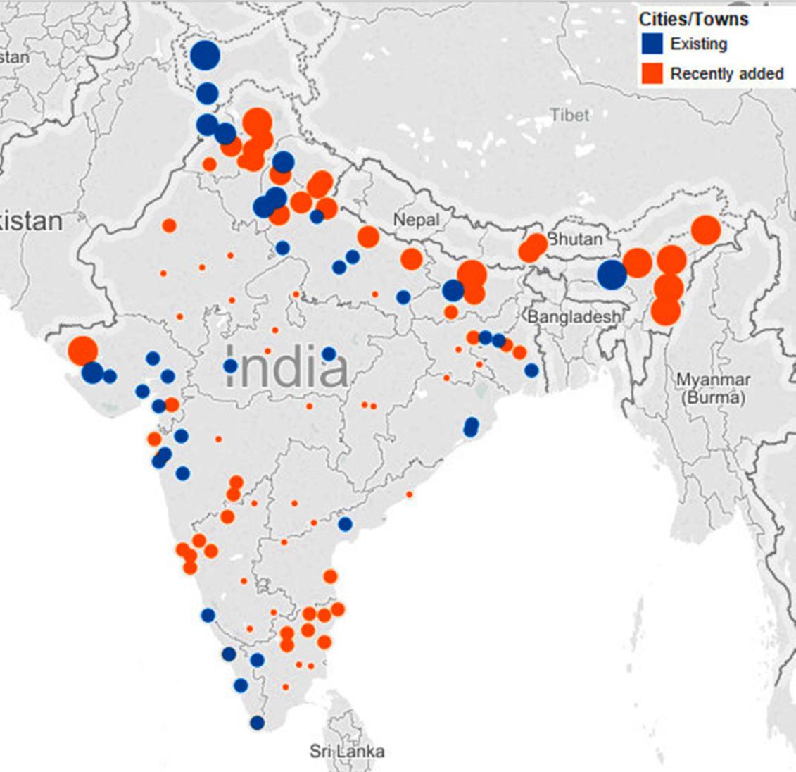
Seismic Zones In India
The Bureau of Indian Standard has grouped the country into four seismic zones
Intensity of earthquakes in different zones
The Bureau of Indian Standard has grouped the country into four seismic zones
Intensity of earthquakes in different zones
| Seismic Zone | Intensity on Modified Mecalli Scale | Areas |
| Zone V
(Very severe intensity zone)
| IX (and above) | Entire northeastern India, parts of Jammu and Kashmir, Himachal Pradesh, Uttaranchal, Rann of Kutch in Gujarat, parts of North Bihar and Andaman & Nicobar Islands. |
| Zone IV
(Severe intensity zone)
| VIII | The remaining parts of Jammu & Kashmir and Himachal Pradesh, Union Territory of Delhi, Sikkim, northern parts of Uttar Pradesh, Bihar and West Bengal, parts of Gujarat and small portions of Maharashtra near the west coast and Rajasthan. |
| Zone III
(Moderate intensity zone)
| VII | Kerala, Goa, Lakshadweep islands, and remaining parts of Uttar Pradesh, Gujarat and West Bengal, parts of Punjab, Rajasthan, Madhya Pradesh, Bihar, Jharkhand, Chhattisgarh, Maharashtra, Orissa, Andhra Pradesh, Tamilnadu and Karnataka. |
| Zone II
(Low intensity zone)
| VI (or less) | The remaining parts of the country. |
2.0 Seismic Force and its nature

While the gravitational forces (dead weights, moving weights, weight from temporary structures) act downward, the wind forces act horizontal across the height of a structure. The seismic (or earthquake) forces are nothing but horizontal motion of the ground and it acts only at the base of a structure. Moreover while gravitational and wind forces are continuous (with respect to time) seismic forces are momentary and lapse only few milliseconds. Also the aftershocks of the earthquake act on the building on and off for several days.
3.0 Stiffness, Ductility& Tensile Testing
By definition Stiffness (k) = Force / Displacement

By definition Stiffness (k) = Force / Displacement
Hence ductility will be inverse of stiffness i.e. 1/ k.
So Ductility is the amount of elongation for a unit increase in force.
A RCC structure can be made ductile in two ways:
1. By doing ductile design and detailing – In local and remote places the expertise is not available
2. By using ductile material – Concrete and brick cannot be ductile, hence only reinforcement can be ductile.
The rebars available in Indian market are ductile steel with elongation percentage of 12% and utilization ratio of 1.12. There is a new grade of steel which has elongation percentage of 18% and utilization ratio of 1.15. This new grade is called Super Ductile.
The properties of a super ductile thermo-mechanically treated rebar are as follows:
| Parameter | Fe 500D
(Ductile)
| Fe 500SD
(Super Ductile)
| BS 4449
500B
| BS4449
500C
| AUS / NZ
500N
| AUS / NZ
500E
|
| Yield Stress (in MPa) | 500 | 500 | 500 | 500 | 500 | 500 |
| Ultimate Tensile Stress (in MPa) | 560 | 575 | 650 | 650 | 650 | 600 |
| Utilization Ratio (UTS / YS) | 1.12 | 1.15 | 1.08 | 1.15 | 1.08 | 1.15 |
| Total Elongation (in %) | 12 | 18 | 5 | 7.5 | 5 | 10 |
A brief definition of all the terms defining the mechanical properties of rebars:
YS – (Yield Stress) is the stress at which a 0.2% of plastic deformation is produced in steel rebar in tension.
UTS – (Ultimate Tensile Stress) is the maximum amount of stress sustained by a rebar in a tensile test before rupture.
Utilization ratio is the ratio of UTS and YS.
% Elongation is the ratio of total elongation of rebar and its original length expressed in percentage.
Utilization ratio and % Elongation together gives an estimate of amount of energy absorbed by the rebar specimen in a tensile strength before failure. (This is clear in the graph below)
While in Limit State and Working stress design methods, the strength of the steel guides the main reinforcement and its consumption, the ductility of reinforcement is important in calculating the shear bearing capacity of the structure. IS 13920 clearly specifies for ductile design, the elongation of rebar should be 14.5% and confirming to IS 1786.
GENERAL SPECIFICATION
The design and, construction of reinforced concrete buildings shall be governed by the provisions of IS 456 : 1978, except as modified by the provisions of this code.
The design and, construction of reinforced concrete buildings shall be governed by the provisions of IS 456 : 1978, except as modified by the provisions of this code.
For all buildings which are more than 3 storeys in height, the minimum grade of concrete shall be M20 (fcL = 20 MPa).
Steel reinforcements of grade Fe 415 (see IS 1786 : 1985) or less only shall be used.
However, high strength deformed steel bars, produced by the thermo-mechanical treatment process, of grades Fe 500 and Fe 550, having elongation more than 14.5 percent and conforming to other requirements of IS 1786 : 1985 may also be used for the reinforcement.

Characteristic curve for Fe 500D & Fe 500SD grade of rebar (during tensile testing)
For details of tensile testing one can refer to:
IS: 1608 Mechanical Testing of Metals – Tensile Testing
IS: 1786 High Strength Steel Bars and Wires for Concrete Reinforcement – Specification
IS: 1608 Mechanical Testing of Metals – Tensile Testing
IS: 1786 High Strength Steel Bars and Wires for Concrete Reinforcement – Specification
Thankful to Er Priyanka Gupta
======================================================
Safety / Stability of RCC structure during earthquake – A challenge to overcome
India has been plagued by some catastrophic earthquake tremors in past that have caused loss of property and human beings:
| Date | Location | Effect | Magnitude |
| January 3, 2016 | North East India | 11 dead, 200 injured | 6.7 |
| May 12, 2015 | Northern India, North East India, Bihar West Bengal (Epicenter at Nepal) | 218 (44 killed in India) | 7.3 |
| April 25, 2015 | Northern India, North East India, Gujarat (Epicenter at Nepal) | 8,900+ | 7.8 |
| September 18, 2011 | North East India, Gangtok, tremors felt in Delhi, Kolkata, Lucknow and Jaipur | 118 | 6.9 |
| October 8, 2005 | Kashmir | 1,30,000 | 7.6 |
| December 26, 2004 | Third deadliest earthquake in the history of the world, the tsunami generated off west coast northern Sumatra, India, Sri Lanka, Maldives | 283106 (15000 killed in India) | 9.1 |
| January 26, 2001 | Gujarat | 20,000 | 7.6/7.7 |
However, during the earthquake in New Zealand on 3rd September 2010 (magnitude on Richter’s scale: 7.0), only 2 people were injuredwhich was caused by falling masonry and glass. Interestingly, the said earthquake had struck when most people were asleep. Therefore it is clear that “EARTHQUAKES DON’T KILL PEOPLE, BUILDINGS DO!”
According to BIS 1893-1966 (Criteria for Earthquake Resistant Design of Structures), India was divided into 7 seismic zones, zone-0 to zone-VI. Later,In BIS 1893-1970, it was revised to zone-I to zone-V. Now, as per the latest version of BIS 1893-2002, zone-I has been merged with zone-II, and only seismic zones II to V exist (refer Figure 1) in India, where zone-II is the least earthquake prone zone, and zone-V is the highest.
Table 1: Zoning of India and corresponding Richter’s magnitude
| Seismic Zone | Mercalli Intensity Scale (MSK64) | Richter’s magnitude |
| II | VI (or less) | Upto 4.9 |
| III | VII | 5.0-5.9 |
| IV | VIII | 6.0-6.9 |
| V | IX (and above) | 7.0 and above |

Figure1 : Seismic zoning of India as per BIS1893-2002
HOW TO MAKE OUR BUILDING/STRUCTURE SAFE AGAINST EARTHQUAKE?
1. Proper seismic loading analysis (static and dynamic) as per BIS1893, load combinations and subsequent design engineering of various structural elements (footing, column, beam, slab, tie beam etc). [software namely ETABS, SAFE, STAAD Pro are the prevalent tools for analysis and engineering design]
1. Proper seismic loading analysis (static and dynamic) as per BIS1893, load combinations and subsequent design engineering of various structural elements (footing, column, beam, slab, tie beam etc). [software namely ETABS, SAFE, STAAD Pro are the prevalent tools for analysis and engineering design]
2. Proper detailing of structural elements as per BIS13920:1993, reaffirmed 2003 (Ductile detailing of RC Structures Subject to Seismic Forces), which is applicable for seismic zones III, IV and V.
3. Retrofitting of existing structures supported on load bearing masonry walls.
SALIENT POINTS OF BIS1893 AND BIS13920 THAT SHOULD BE CONSIDERED DURING DESIGN ENGINEERING/DETAILING/CONSTRUCTION OF NEW RCC BUILDINGS/STRUCTURES LOCATED IN SEISMIC ZONES III, IV & V:
• During design using BIS1893, the structure should be designed as OMRF (Ordinary Moment Resisting Frame), if it is designed and detailed as per BIS456:2000, but not meeting ductile detailing requirement of BIS13920. However, if specially detailed to provide ductile behavior and comply to requirements of BIS13920, the structure should be designed as SMRF (Special Moment Resisting Frame), where R (response reduction factor, defined in BIS1893) is higher than that for OMRF, thus considering considerably less seismic base shear and making the structure more ductile and resistant to earthquake.
• During design using BIS1893, the structure should be designed as OMRF (Ordinary Moment Resisting Frame), if it is designed and detailed as per BIS456:2000, but not meeting ductile detailing requirement of BIS13920. However, if specially detailed to provide ductile behavior and comply to requirements of BIS13920, the structure should be designed as SMRF (Special Moment Resisting Frame), where R (response reduction factor, defined in BIS1893) is higher than that for OMRF, thus considering considerably less seismic base shear and making the structure more ductile and resistant to earthquake.
• On analysis, storey drift should never exceed (Storey height/250), as per BIS1893.
• Minimum grade of concrete to be used should be M20.
• High yield strength deformed steel bars, produced by the thermo-mechanical treatment process of grades Fe 500 and Fe 550 having elongation more than 14.5% and conforming to other requirements of BIS1786:2008 may be used for the reinforcement.
• Any reinforcement bar having higher elongation percent and UTS: YS ratio possesses better ductility. Thus satisfying Table 3 of BIS1786:2008, Fe500D and Fe550D use is advisable, where minimum elongation percent requirement is greater than 14.5%. Tata Tiscon has Fe500D rebar grade in market. The properties requirement of Fe500D as per BIS1786, and the properties available in Tata Tiscon Fe500D are given as follows:
| Mechanical/Chemical Properties | Unit | BIS 1786 Fe500D requirement | TATA TISCON Fe500D properties |
| Carbon | % | 0.250 max | 0.250 max |
| Carbon Equivalent (C + Mn /6) | % | 0.420 max | 0.400 max |
| Sulphur | % | 0.040 max | 0.035 max |
| Phosphorous | % | 0.040 max | 0.035 max |
| S + P | % | 0.075 max | 0.070 max |
| Yield strength (YS) | MPa | 500 min | 500 min |
| Ultimate Tensile strength (UTS) | MPa | 565 min | 580 min |
| UTS/YS | Ratio | 1.10 min | 1.12 min |
| Total Elongation | % | 16 min | 18 min |
• Apart from Fe500D grade, Tata Tiscon has “SD” (Super Ductile) grade of rebar, where “SD” is confirming to Fe500D requirements of BIS1786-2008, only having higher UTS/YS ratio, and hence better for highly seismic prone areas in India. However, “SD” grade of rebar is available at selected locations in India, which are highly seismic prone and generally falls in seismic zones IV and V. The features and properties requirement of “SD” versus “500D” grade is shown below. [refer Figures2 & 3]

Figure2 : Fe500D vs SD (Higher UTS for same YS)
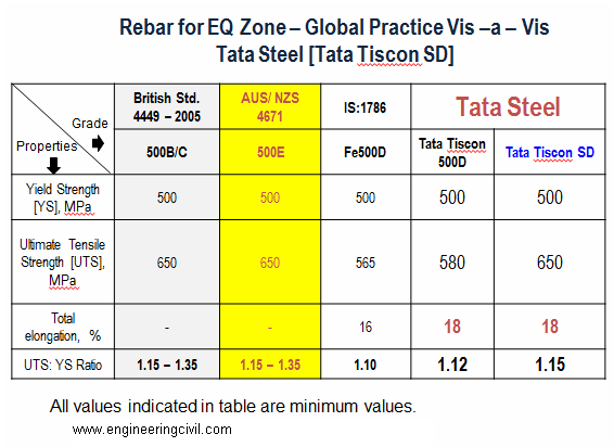
Figure3 : Fe500D vs SD properties
• Anchorage of beam longitudinal bars beyond column face in an external beam-column joint = Ld + 10d, where Ld = development length in tension as per Cl. 26.2.1 of BIS456:2000, d = nominal dia of rebar. [refer Figure4]
• At location of rebar splice (lap), centre-to-centre spacing of stirrups should not exceed 150 mm. [refer Figure5]
• Minimum and maximum percentage of longitudinal reinforcement in beam should satisfy requirements of BIS13920. As shown in Figure 6, the spacing of stirrups should be satisfied. However, nowhere spacing of hoops should be less than 100 mm. Minimum dia of hoop bar should be 6 mm. In beams with clear span exceeding 5m, the minimum bar dia should be 8mm.

Figure 4

Figure 5
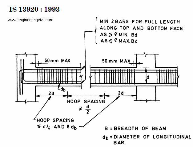
Figure 6
• Stirrups with 135o hook bend and 10d (>75mm) hook length should be mandatory used as per BIS13920. [refer Figure7] In this endeavor, Tata Tiscon have come up with such ready-made stirrups (Brand name: Super-links) available in all dealer counters across India.
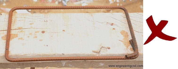
Figure7: Wrong practice as per BIS13920

Figure7a: Correct practice as per BIS13920
• Special confining reinforcement should be provided in form of stirrups in all beam-column joints and column-footing joints, as per the provisions and clauses given in BIS13920. [refer Figure8]
• The spacing of hoops used as special confining reinforcement shall not exceed 1/4 of minimum member dimension but need not be less than 75 mm nor more than 100 mm.
• Shear walls are integral part of lateral load resisting system of the structure, and to show ductile behaviour, should be designed and detailed as per provisions and clauses given in BIS1893 and BIS13920.
• Percentage of permissible increase in Allowable Bearing Pressure, Resistance in soils, and minimum N-values (SPT value, i.e, standard penetration test value of soil) should satisfy table 1 of BIS1893.

Fig 8: Special confining reinforcement provisions as per BIS13920
Disclaimer: This document aims only at highlighting good construction practises and meaningful applications to make RCC structures with proper safety/stability considerations. In any case the desired result is not obtained on following the write-up, the author shall not be responsible.
Thankful to Sir Sourav Dutta
=====================================================
Things Site Engineers Must Know About Reinforcement and Steel Bars
As Per Indian Guidelines Only.
Clear cover to main reinforcement in
Footings : 50 mm
Raft foundation Top : 50 mm
Raft foundation Bottom/ sides : 75 mm
Strap Beam : 50 mm
Grade Slab : 20 mm
Column : 40 mm (d>12mm) 25 mm (d= 12mm)
Shear Wall : 25 mm
Beams : 25 mm
Slabs : 15 mm or not less than diameter of the bar.
Flat Slab : 20 mm
Staircase : 15 mm
Retaining Wall on Earth : 20/ 25 mm
Water retaining structures : 20 / 30 mm
Sunshade (Chajja) : 25 mm
Hook for stirrups is 9D for one side
No. of stirrups = (clear span/Spanning) + 1
For Cantilever anchorage length for main steel is 69D
“L” for column main rod in footing is minimum of 300mm
Chairs of minimum 12 mm diameter bars should be used.
Minimum diameter of dowel bars should be 12 mm
Lap slices should not be used for bar larger than 36 mm.
In steel reinforcement binding wire required is 8 kg per MT.
Lapping is not allowed for the bars having diameters more than 36 mm.
Minimum number of bars for a square column are 4 and for circular column are 6.
Longitudinal reinforcement should not be less than 0.8% and more than 6% of gross C/S.
Weight of rod per meter length = d2/162 where d is the diameter in mm
All reinforcement shall be free from mill scales, loose rust & coats of paints, oil or any other substances.
Main bars in the slabs shall not be less than 8 mm (HYSD) or 10 mm (Plain bars) and the distributors not less than 8 mm and not more than 1/8 of slab thickness.
In case of spacing of bars
Provide the diameter of the bar, if the diameter of the bar are equal.
Provide the diameter of the larger bar, if the diameter are unequal.
5mm more than the nominal maximum size of the coarse aggregate.
Provide the diameter of the bar, if the diameter of the bar are equal.
Provide the diameter of the larger bar, if the diameter are unequal.
5mm more than the nominal maximum size of the coarse aggregate.
=====================================================
What are the reasons for establishing minimum distance between bars and maximum distance between bars?
In some codes, a minimum distance between bars is specified to allow for sufficient space to accommodate internal vibrators during compaction.
On the other hand, the restriction of maximum bar spacing is mainly for controlling crack width. For a given area of tension steel areas, the distribution of steel reinforcement affects the pattern of crack formation. It is preferable to have smaller bars at closer spacing rather than larger bars at larger spacing to be effective in controlling cracks. Hence, the limitation of bar spacing beyond a certain value (i.e. maximum distance between bars) aims at better control of crack widths.
This question is taken from book named – A Self Learning Manual – Mastering Different Fields of Civil Engineering Works (VC-Q-A-Method) by Vincent T. H. CHU.
What is the purpose of critical steel ratio in concrete structures?
The purpose of critical steel ratio is to control the cracking pattern by having concrete failing in tension first. If steel reinforcement yields first before the limit of concrete tensile strength is reached, then wide and few cracks would be formed. In the calculation of critical steel ratio, the thickness of the whole concrete section is adopted for analysis. However, if the concrete section exceeds 500mm in thickness, only the outer 250mm concrete has to be considered in calculating minimum reinforcement to control thermal and shrinkage cracks. It is because experimental works showed that for concrete section greater than 500mm, the outer 250mm on each face could be regarded as surface zone while the remaining could be regarded as core. The minimum reinforcement to control cracking should therefore be calculated based on a total maximum thickness of 500mm.
This question is taken from book named – A Self Learning Manual – Mastering Different Fields of Civil Engineering Works (VC-Q-A-Method) by Vincent T. H. CHU.
What are the potential problems of excessive concrete covers?
In reinforced concrete structures cover is normally provided to protect steel reinforcement from corrosion and to provide fire resistance. However, the use of cover more than required is undesirable in the following ways:
(i) The size of crack is controlled by the distance of longitudinal bars to the point of section under consideration. The closer a bar is to this point, the smaller is the crack width. Therefore, closely spaced bars with smaller cover will give narrower cracks than widely spaced bars with larger cover. Consequently, with an increase in concrete cover the crack width will increase.
(ii) The weight of the concrete structure is increased by an increase in concrete cover. This effect is a critical factor in the design of floating ships and platforms where self-weight is an important design criterion.
(iii) For the same depth of concrete section, the increase of concrete cover results in the reduction of the lever arm of internal resisting force.
This question is taken from book named – A Self Learning Manual – Mastering Different Fields of Civil Engineering Works (VC-Q-A-Method) by Vincent T. H. CHU.
Increase in cost of construction materials: A challenge to overcome
By
Sourav Dutta
Manager-Civil
Ion Exchange India Limited
Sourav Dutta
Manager-Civil
Ion Exchange India Limited
Construction industry at present is facing a major hike in material price, especially cement, sand and stone chips. The following document is prepared to highlight the reduction in concrete manufacturing cost upon using Fly Ash (BIS3812). The method of mix design has been done in reference with BIS10262-2009. Hope that any contractor over India will benefit from the given working and follow the suggested method to reduce their construction cost.
This will have the following advantages: (1) Reduction in use of construction materials which are facing scarcity now-a-days, (2) Reduction of construction cost for contractor, (3) Use of fly ash in a effective manner, which are generated as waste product from thermal power plants and various industrial plants, (4) Assisting in scientific disposal of waste product from thermal power plants and various industrial plants.
Assumed parameters for RCC M25 per Cum mix design as per IS10262:2009 :
Exposure= Moderate
Quality control at site= Fair
Method of concrete placing= Pumping
Grade of cement= 43
Grading zone of sand= Zone 2
Type of aggregate= Saturated surface dry aggregate
Nominal maximum size of aggregate= 20mm
Chemical Admixture (IS 9103)= None
Exposure= Moderate
Quality control at site= Fair
Method of concrete placing= Pumping
Grade of cement= 43
Grading zone of sand= Zone 2
Type of aggregate= Saturated surface dry aggregate
Nominal maximum size of aggregate= 20mm
Chemical Admixture (IS 9103)= None

Assumed parameters for RCC M30 per Cum mix design as per IS10262:2009 :
Exposure= Severe
Quality control at site= Fair
Method of concrete placing= Pumping
Grade of cement= 43
Grading zone of sand= Zone 2
Type of aggregate= Saturated surface dry aggregate
Nominal maximum size of aggregate= 20mm
Chemical Admixture (IS 9103)= None
Exposure= Severe
Quality control at site= Fair
Method of concrete placing= Pumping
Grade of cement= 43
Grading zone of sand= Zone 2
Type of aggregate= Saturated surface dry aggregate
Nominal maximum size of aggregate= 20mm
Chemical Admixture (IS 9103)= None
 Thankful to Er. Sourav Dutta
================================================
Bridges & Highways Engineering & Maintenance Summit 2017
Event Description:
Bridges and Highways infrastructure development have rapidly escalated in recent years in Asia Pacific, constituting 60% of the global market. Demand is largely driven by the availability of government road building funds, urbanization growth, and the need to replace or repair aging infrastructure. The Engineering and Maintenance components play a vital role in bridges & highways development as they are key to overall safety, project management and delivery of bridge and highway project and on a larger scale, a reflection of the country’s infrastructure plans and reputation.
If you are involved in Bridges & Highways Engineering & Maintenance, then make sure you do not miss out on Equip Global’s Bridges & Highways Engineering and Maintenance Summit 2016. It provides an exclusive platform that brings together Project Directors, Ministry of Infrastructure, Head of Civil Engineers and Head of Design Engineering to discuss on innovative design and engineering of bridges & highways, maximize lifespan through effective maintenance as well as latest technology involved in bridges and highways projects for better project management, engineering and cost optimization.
===================================================
11th Airfield Engineering & Maintenance Summit 2016
World’s Leading Airfield Engineering & Maintenance Summit Returns to London UK!
Equip Global’s Airfield Engineering & Maintenance Summit (AEMS) has established itself as the world’s foremost and leading event of its kind. As the world’s largest meeting place for key industry stakeholders, every year, C-Level Executives, Heads of Engineering, Heads of Assets & Civil Works, Heads of Construction and Heads of Aerodrome/Airside Operations amongst other senior decision makers in airfield engineering & maintenance gather to discuss the latest technologies, techniques, strategies and best practices in the industry.
Get ready to:
1. Hear from renowned Airfield Pavement Experts who have worked on hundreds of airfield pavement engineering & maintenance projects globally!
2. Track recent & upcoming projects, ongoing airfield pavement engineering & maintenance updates, Airfield Rehabilitation & Overlay Project experiences and hear practical information and experiences of actual airfield engineering, design & construction case studies from airport operators & aviation authorities globally
3. Learn practical tips and know-hows on how to maintain pavements of various materials and under different climatic/temperature conditions, pavement condition monitoring and schedule maintenance works to meet operational demands
4. Hear and Witness Latest Innovations and Best Practices in rubber removal, maintenance of bleeding & flushed pavements, asphalt/concrete/bitumen pavement maintenance and ACN-PCN Systems
5. Network with the Industry Who’s Who & Airport/Aviation AuthorityDecision Makers Globally
No comments:
Post a Comment