Complete Report on Failure Analysis of World Trade Center
Research Papers
By
Kevin J. LaMalva
Simpson Gumpertz & Heger, Inc.
Kevin J. LaMalva
Simpson Gumpertz & Heger, Inc.
Abstract
This research involves a failure analysis of the internal structural collapse that occurred in World Trade Center 5 due to fire exposure alone on September 11, 2001. It is hypothesized that the steel column-tree assembly failed during the heating phase of the fire. Abaqus/Standard was used to predict the structural performance of the assembly when exposed to the fire. Results from a finite element, thermal-stress model confirms this hypothesis, for it is concluded that the catastrophic, progressive structural collapse occurred approximately 2 hours into the fire exposure.
This research involves a failure analysis of the internal structural collapse that occurred in World Trade Center 5 due to fire exposure alone on September 11, 2001. It is hypothesized that the steel column-tree assembly failed during the heating phase of the fire. Abaqus/Standard was used to predict the structural performance of the assembly when exposed to the fire. Results from a finite element, thermal-stress model confirms this hypothesis, for it is concluded that the catastrophic, progressive structural collapse occurred approximately 2 hours into the fire exposure.
Keywords:
Collapse, Coupled Analysis, Failure, Fire, Heat Transfer, Interface Friction, Structural, Thermal-Stress, World Trade Center (WTC)
Collapse, Coupled Analysis, Failure, Fire, Heat Transfer, Interface Friction, Structural, Thermal-Stress, World Trade Center (WTC)
1. Background
World Trade Center 5 (WTC 5) was a nine-story building in the World Trade Center complex in New York City, NY (Figure 1). On September 11, 2001, flaming debris from the World Trade Center Tower collapses ignited fires in WTC 5. These fires burned unchecked, ultimately causing a localized interior collapse from the 8th floor to the 4th floor in the eastern section of the building (Figure 2). Debris impact was not a direct factor in this failure; the collapse was caused by fire alone.
The structural design of WTC 5 employed a common framing configuration, with steel column-tree assemblies that had beam stubs welded to the columns and cantilevering to support simple-span girders. The connections between the girders and the beam stubs were shear plates attached to the webs with bolts. The floor framing was topped with a concrete slab with welded wire fabric reinforcement.
Forensic evidence suggests that the collapse occurred during the heating phase of the fire. The columns remained straight and freestanding after the collapse (Figure 2), suggesting that the girders never developed catenary action that would have pulled columns inward, particularly as the girders cooled late in the fire. In general, the timing of this failure (early in the fire when occupants and firefighters could be in the building and therefore at great risk) is not typical for steel structures.


2. Finite Element Analysis Approach
For this research, the nonlinear heat transfer and stress analysis capabilities of Abaqus/Standard allowed study of the mechanisms that caused WTC 5 to suffer an internal collapse. The structural plans and details of WTC 5 provided the data for an accurate model of the structural configuration.
For this research, the nonlinear heat transfer and stress analysis capabilities of Abaqus/Standard allowed study of the mechanisms that caused WTC 5 to suffer an internal collapse. The structural plans and details of WTC 5 provided the data for an accurate model of the structural configuration.
The process involved sequentially coupled thermal-stress analyses with a heat transfer simulation to determine temperature history, followed by a stress analysis that incorporated the temperature history as part of the loading. The analyses modeled four structural bays on the 8th floor of WTC 5 (a typical bay is shown in Figure 3) using the mesh detail shown in Figure 4 for both models.


2.1 Heat Transfer Analysis
The model included common spray-applied mineral fiber fireproofing insulation as shown in Figure 4, in which the thermal contact between the insulation and steel, as well as the temperature-dependent properties of A36 steel, were derived from literature.
The model included common spray-applied mineral fiber fireproofing insulation as shown in Figure 4, in which the thermal contact between the insulation and steel, as well as the temperature-dependent properties of A36 steel, were derived from literature.
The 2005 National Institute of Standards and Technology (NIST) report on the performance of the World Trade Center Towers (WTC 1 and WTC 2) provided the basis for the effective heat of combustion and the peak heat release rate of the fire that occurred within WTC 5. The time function of the heat release rate became the input for a Consolidated Fire and Smoke Transport Model (CFAST, developed by NIST) analysis to estimate the upper gas layer temperature history of the fire.
A convective film condition on the faces of the assembly exposed to the fire environment modeled the thermal loading, using a heat transfer coefficient characteristic of turbulent, natural convective heating. Subsequently, the results of the CFAST simulation prescribed the sink temperature history of the model.
2.2 Stress Analysis
The three-dimensional temperature distribution history of the steel assembly based on the heat transfer analysis became part of the loading in the stress analysis. Other loads applied to the model included gravity to model the weight and 39 kips of pretension in each bolt to produce an idealization of the static and kinetic friction conditions at the connection.
The three-dimensional temperature distribution history of the steel assembly based on the heat transfer analysis became part of the loading in the stress analysis. Other loads applied to the model included gravity to model the weight and 39 kips of pretension in each bolt to produce an idealization of the static and kinetic friction conditions at the connection.
The model utilized nonlinear, temperature-dependent stiffness and thermal expansion properties of A36 steel based on experimental data (Harmathy, 1993). Therefore, the temperature distribution history dictated the steel strength and stiffness properties. The nonlinear material properties, together with modeling to account for geometric nonlinearities, produced high-fidelity analyses of structural performance during the fire.
2.3 Failure Criterion Analysis
Forensic evidence suggests that the shear connection failures in WTC 5 were due to rupture of the web portion of the beam stems. This type of failure occurs when the bolts bear against the weak side (i.e., acting toward the free end of the member) of the bolt holes. Bearing stress of this type causes shear planes to form in the web steel. Finally, cracks along the shear planes cause catastrophic failure of the shear connection.
Forensic evidence suggests that the shear connection failures in WTC 5 were due to rupture of the web portion of the beam stems. This type of failure occurs when the bolts bear against the weak side (i.e., acting toward the free end of the member) of the bolt holes. Bearing stress of this type causes shear planes to form in the web steel. Finally, cracks along the shear planes cause catastrophic failure of the shear connection.
A simple model consisting of a single bolt and holes in connected plates provided data on the material strain condition at the point of catastrophic rupture. A failure load, derived using the AISC Steel Manual of Steel Construction (2001), applied to the single bolt model produced the required strain data. The plastic shear strain for the failure load produced the failure criterion for the full connection models.
3. Simulation Results
The temperature distribution near a shear connection after two hours of fire exposure is shown in Figure 5. In general, the average temperature of the steel agrees well with estimates from hand calculations. The results of the thermal model show that the insulation delayed the transmission of heat to the steel during the fire exposure as anticipated. Moreover, the results show that the upper region of the steel assembly remained cooler due to the heat sink effect of the overhead concrete slab.
The temperature distribution near a shear connection after two hours of fire exposure is shown in Figure 5. In general, the average temperature of the steel agrees well with estimates from hand calculations. The results of the thermal model show that the insulation delayed the transmission of heat to the steel during the fire exposure as anticipated. Moreover, the results show that the upper region of the steel assembly remained cooler due to the heat sink effect of the overhead concrete slab.
The temperature of the beam stems at the shear connection was approximately 400 °C hotter than at the column after two hours of fire exposure. The beam stem was exposed uniformly to the hot gases and began to heat in accordance with its heat transfer properties. The cooler column (and adjacent structure) acted as a heat sink that tended to moderate the temperature rise of the beam stem immediately adjacent to the column. The shear connection was located far enough from this critical heat sink that it remained relatively unaffected, and quickly rose in temperature along with the simple-span girder.
As the steel in the compartment heated in the first hour of fire exposure, it expanded, causing the floor girder to elongate significantly and close the gap between it and the beam stem. This elongation caused relatively harmless compressive stress concentrations as the bolts pushed into the beam stem web.
As the temperature of the steel assembly increased further, the frame rigidity decreased steadily,causing the floor girders to deflect significantly. This deflection caused the lower flange of the girder to contact and deform the beam stem web, forming a fulcrum at the contact point. After about two hours of fire exposure, the loss of rigidity in the steel “outpaced” its thermal expansion, and the top bolt of the shear connection, which was pushing into the web, started to pull toward the end of the beam stem web (Figure 6).


4. Discussion of Results
According to the failure criterion derived and the results of the thermal-stress analysis, the heat-weakened shear connection experienced complete failure after approximately two hours of fire exposure. The deformation and failure of the shear connection predicted by the Abaqus model are very similar to those exhibited in failed connections in WTC 5. The angles at which the bolts pried against the bolt holes are similar in the model and the specimen (Figure 7). Moreover, photographs of failed beam stems show web deformations indicative of the fulcrum action.
According to the failure criterion derived and the results of the thermal-stress analysis, the heat-weakened shear connection experienced complete failure after approximately two hours of fire exposure. The deformation and failure of the shear connection predicted by the Abaqus model are very similar to those exhibited in failed connections in WTC 5. The angles at which the bolts pried against the bolt holes are similar in the model and the specimen (Figure 7). Moreover, photographs of failed beam stems show web deformations indicative of the fulcrum action.

5. Conclusion
The sequentially-coupled, nonlinear thermal-stress modeling capabilities in Abaqus/Standard allowed study of the structural behaviors that led to the internal collapse of WTC 5. The analysis show that this collapse occurred approximately two hours into the heating phase of the fire after the simple span girders deflected enough to tear the connecting bolts out of the webs. It is not the precise time of failure which is aramount, but the fact that the structure failed uncharacteristically during the fire’s heating phase, rather than during the cooling phase when most fire-induced collapses occur.
The sequentially-coupled, nonlinear thermal-stress modeling capabilities in Abaqus/Standard allowed study of the structural behaviors that led to the internal collapse of WTC 5. The analysis show that this collapse occurred approximately two hours into the heating phase of the fire after the simple span girders deflected enough to tear the connecting bolts out of the webs. It is not the precise time of failure which is aramount, but the fact that the structure failed uncharacteristically during the fire’s heating phase, rather than during the cooling phase when most fire-induced collapses occur.
The fire that caused structural collapse in WTC 5 was a severe, complete burn-out fire. As such, it is not unreasonable that the structure would experience substantial damage. However, the failure of the building to achieve the preferred performance, with the framing system surviving at least into the cooling phase of the fire, follows from the absence of analyses and design for fire exposure.
The present approach to fire protection engineering in much of the United States is primarily prescriptive, often employing propriety products to insulate structural elements and active fire suppression systems to control fire growth. Such approaches would not lead to an appreciation for vulnerabilities such as apparently existed in some of the detailing in WTC 5.
Analytical, performance-based approaches, more akin to common design for wind, seismic, and other environmental loads, are more likely to reveal critical aspects of building performance in fires, and provide engineers with the understanding they need to create designs that are robust, raise safety for occupants and firefighters, and are cost efficient.
Accurate, detailed finite element modeling can be used to assess the fire endurance of steel structures. Such simulations can be used to develop pre-engineered solutions to building codes. Additionally, knowledge of the fire endurance behavior of WTC 5 can further the understanding of firefighting risk in existing buildings of similar design.
In the case of WTC 5, relatively simple detailing changes would have enhanced the structure’s fire resistance. Slotted holes in the girder webs or increased spacing between the end of the girder stubs and the beginning of the simply supported center spans would have allowed more girder rotation without developing the prying action that tore out the girder webs. Keeping the shear connection near the face of the column would have reduced the temperature of this critical connection, thereby maintaining higher temperature-induced tear-out strengths during the fire.
In the more general case, we must acknowledge that many buildings in current use have unappreciated vulnerabilities. While analyzing and retrofitting for these vulnerabilities in existing buildings could be undertaken if justified for certain framing systems (e.g., perhaps for column-tree assemblies, if risk analyses and system testing verified heightened risk for the building system generally), finding the critical shortcomings in the present building stock would be a prohibitive exercise. However, modest expenditures of engineering effort during the design phase for new buildings can reveal fire performance weaknesses that can be avoided, often at minimal cost to construction.
6. References
1. Manual of Steel Construction: Load and Resistance Factor Design, 3rd ed., American Institute of Steel Construction (AISC), 2001
2. Harmathy, T.Z., “Fire Safety Design and Concrete,” Longman Scientific and Technical, United Kingdom, 1993
3. World Trade Center Building Performance Study: Data Collection, Preliminary Observations, and Recommendations, Federal Emergency Management Agency (FEMA), New York, 2002
We are thankful to Sir Matthew Ladzinski for submitting this report to engineeringcivil.com and also granting us rights to publish it on web. This report will help all civil engineers study the Failure Analysis of World Trade Center 5..
=======================================================
Minneapolis I-35W Bridge Collapse – Engineering Evaluations and Finite Element Analysis
Posted in Civil Engineering Disasters, Research Papers | Email This Post |
by Carl R. Schultheisz, Alan S. Kushner (National Transportation Safety Board), Toshio Nakamura (State University of New York, Stony Brook), Justin Ocel (Federal Highway Administration), William Wright (Virginia Polytechnic Institute and State University) and Min Li (SIMULIA Central)
Abstract
The National Transportation Safety Board (NTSB) investigates accidents to identify the probable cause and to make recommendations that would prevent similar accidents. Following the collapse of the I-35W bridge in Minneapolis on August 1, 2007, the NTSB worked with the Federal Highway Administration, the Minnesota Department of Transportation and other parties with information and expertise, including SIMULIA Central, to determine the circumstances that contributed to the collapse of the bridge, completing the investigation in 15 months. The NTSB concluded that the collapse of the bridge was caused by the inadequate load capacity of gusset plates used to connect the truss members, as a result of an error by the bridge design firm, Sver-drup & Parcel and Associates, Inc. The loading conditions included a combination of (1) substantial increases in the weight of the bridge caused by previous bridge modifications, and (2) the traffic and concentrated construction loads on the bridge on the day of the collapse. Evidence from the collapsed bridge structure, engineering evaluations of the design, and results from the finite element analyses used to support the investigation are reviewed.
The National Transportation Safety Board (NTSB) investigates accidents to identify the probable cause and to make recommendations that would prevent similar accidents. Following the collapse of the I-35W bridge in Minneapolis on August 1, 2007, the NTSB worked with the Federal Highway Administration, the Minnesota Department of Transportation and other parties with information and expertise, including SIMULIA Central, to determine the circumstances that contributed to the collapse of the bridge, completing the investigation in 15 months. The NTSB concluded that the collapse of the bridge was caused by the inadequate load capacity of gusset plates used to connect the truss members, as a result of an error by the bridge design firm, Sver-drup & Parcel and Associates, Inc. The loading conditions included a combination of (1) substantial increases in the weight of the bridge caused by previous bridge modifications, and (2) the traffic and concentrated construction loads on the bridge on the day of the collapse. Evidence from the collapsed bridge structure, engineering evaluations of the design, and results from the finite element analyses used to support the investigation are reviewed.
Keywords: Bridge Collapse, Gusset Plate, Plasticity, Instability, Riks, Fasteners.
Introduction
About 6:05 p.m. central daylight time on Wednesday, August 1, 2007, the eight-lane, 1,907-foot-long I-35W highway bridge over the Mississippi River in Minneapolis, Minnesota, experienced a catastrophic failure in the central deck truss span over the river. The 1,064-foot-long deck truss portion of the bridgecollapsed, along with adjacent sections of the approach spans that were supported by the deck truss. See Figure 1. A total of 190 people were confirmed to have been on or near the bridge when the collapse occurred; 13 people died, and 145 people were injured. There were 111 vehicles on the portion of the bridge that collapsed, with 17 recovered from the water.
About 6:05 p.m. central daylight time on Wednesday, August 1, 2007, the eight-lane, 1,907-foot-long I-35W highway bridge over the Mississippi River in Minneapolis, Minnesota, experienced a catastrophic failure in the central deck truss span over the river. The 1,064-foot-long deck truss portion of the bridgecollapsed, along with adjacent sections of the approach spans that were supported by the deck truss. See Figure 1. A total of 190 people were confirmed to have been on or near the bridge when the collapse occurred; 13 people died, and 145 people were injured. There were 111 vehicles on the portion of the bridge that collapsed, with 17 recovered from the water.

The National Transportation Safety Board (NTSB) launched a team of investigators to the accident scene, with on-scene work beginning on the day after the collapse. The on-scene investigation, including documentation and analysis of the recovered bridge structure, lasted until November 10, 2007. The results of the investigation were presented in the NTSB’s final report [NTSB 2008k], which was adopted on November 14, 2008.
The NTSB is an independent federal agency charged with investigating all aviation accidents in the United States and investigating major accidents involving highways, railroads, pipelines, hazardous materials and marine transportation. The goals of every investigation are to determine the probable cause of the accident and to make recommendations for systemic changes that would prevent similar accidents.
In order to accomplish its mission, the NTSB collaborates with parties involved in the accident who have specialized technical knowledge or expertise that can contribute to the investigation. For the collapse of the I-35W bridge, the parties to the investigation included the Federal Highway Administration (FHWA); the Minnesota Department of Transportation (Mn/DOT) and their consultant Wiss, Janney, Elstner Associates, Inc. (WJE); Jacobs Engineering Group, Inc. (Jacobs), which purchased Sverdrup Corporation (successor to the original bridge design firm) in 1999; and Progressive Contractors, Inc. (PCI), which was repaving part of the deck on the day of the accident.
Bridge design
The I-35W bridge was designed by the engineering consulting firm of Sverdrup & Parcel and Associates, Inc., of St. Louis, Missouri. The design was based on the 1961 American Association of State Highway Officials (AASHO) Standard Specifications for Highway Bridges and 1961 and 1962 Interim Specifications, and on the 1964 Minnesota Highway Department Standard Specifications for Highway Construction. The bridge design was developed over several years. Plans for the foundation were approved in 1964 and construction of some piers began in 1964. The final design plans for the bridge were certified by the Sverdrup & Parcel project manager (a registered professional engineer) on March 4, 1965. The bridge design plans were approved by the Minnesota Highway Department on June 18, 1965.
The I-35W bridge was designed by the engineering consulting firm of Sverdrup & Parcel and Associates, Inc., of St. Louis, Missouri. The design was based on the 1961 American Association of State Highway Officials (AASHO) Standard Specifications for Highway Bridges and 1961 and 1962 Interim Specifications, and on the 1964 Minnesota Highway Department Standard Specifications for Highway Construction. The bridge design was developed over several years. Plans for the foundation were approved in 1964 and construction of some piers began in 1964. The final design plans for the bridge were certified by the Sverdrup & Parcel project manager (a registered professional engineer) on March 4, 1965. The bridge design plans were approved by the Minnesota Highway Department on June 18, 1965.
Bridge construction
The bridge was 1,907 feet long and carried eight lanes of traffic, four northbound and four southbound. The bridge had 13 reinforced concrete piers and 14 spans, numbered south to north. Eleven of the 14 spans were approach spans to the deck truss portion. The bridge deck in the approach spans either was supported by continuous welded steel plate girders or by continuous voided slab concrete spans. The south approach spans were supported by the south abutment; by piers 1, 2, 3, and 4; and by the south end of the deck truss portion. The north approach spans were supported by the north abutment; by piers 9, 10, 11, 12, and 13; and by the north end of the deck truss portion. The 1,064-foot-long deck truss portion of the bridge encompassed a portion of span 5; all of spans 6, 7, and 8; and a portion of span 9. The deck truss was supported by four piers (piers 5, 6, 7, and 8).
The bridge was 1,907 feet long and carried eight lanes of traffic, four northbound and four southbound. The bridge had 13 reinforced concrete piers and 14 spans, numbered south to north. Eleven of the 14 spans were approach spans to the deck truss portion. The bridge deck in the approach spans either was supported by continuous welded steel plate girders or by continuous voided slab concrete spans. The south approach spans were supported by the south abutment; by piers 1, 2, 3, and 4; and by the south end of the deck truss portion. The north approach spans were supported by the north abutment; by piers 9, 10, 11, 12, and 13; and by the north end of the deck truss portion. The 1,064-foot-long deck truss portion of the bridge encompassed a portion of span 5; all of spans 6, 7, and 8; and a portion of span 9. The deck truss was supported by four piers (piers 5, 6, 7, and 8).
The original bridge design accounted for thermal expansion using a combination of fixed and expansion bearings for the bridge/pier interfaces. The fixed bearing assemblies were located at piers 1, 3, 7, 9, 12, and 13. Expansion (sliding) bearings were used at the south and north abutments and at piers 2, 4, 10, and 11. Expansion roller bearings were used at piers 5, 6, and 8.
The deck of the I-35W bridge consisted of two reinforced concrete deck slabs separated by about 6 inches. The total width of the deck slabs was about 113 feet 4 inches. When the bridge was opened to traffic in 1967, the cast-in-place concrete deck slab had a minimum thickness of 6.5 inches. As discussed later in this report, bridge renovation projects eventually increased the average thickness of the concrete deck by about 2 inches.
Deck truss portion of the bridge
In a deck truss bridge, the roadbed is along the top of the truss structure. The deck truss portion of the bridge consisted of two parallel main Warren-type trusses (east and west) with verticals. A Warren truss has alternating tension and compression diagonals and has the advantage that chord members are continuous across two panels, with the same force carried across both panels. This arrangement simplifies some of the design calculations.
In a deck truss bridge, the roadbed is along the top of the truss structure. The deck truss portion of the bridge consisted of two parallel main Warren-type trusses (east and west) with verticals. A Warren truss has alternating tension and compression diagonals and has the advantage that chord members are continuous across two panels, with the same force carried across both panels. This arrangement simplifies some of the design calculations.
The upper and lower chords of the main trusses extended the length of the deck truss portion of the bridge and were connected by straight vertical and (except at each end of the deck truss) diagonal members that made up the truss structure. The upper and lower chords were welded box members, as were those diagonals and verticals that were designed primarily for compression. The vertical and diagonal members designed primarily for tension were H members consisting of flanges welded to a web plate.
Gusset plates were used to connect the truss members. The gusset plates were primarily attached to the truss members with rivets, but a few bolts were used at each joint, presumably to expedite the initial connection during construction.
The east and west main trusses were spaced 72 feet 4 inches apart. The deck was supported by 27 transverse welded floor trusses spaced on 38-foot centers along the main trusses and by two floor beams at the north and south ends. The floor trusses were cantilevered out about 16 feet on either side past the east and west main trusses. The concrete deck for the roadway rested on 27-inch-deep wide-flange longitudinal stringers attached to the transverse floor trusses and spaced on 8-foot-1-inch centers. The 14 stringers were continuous for the length of the deck truss except for five expansion joints. Diaphragms connected the webs of adjacent stringers to transfer lateral loads and maintain structural rigidity and geometry.
The main truss nodes were numbered from the south beginning from 0, reaching node 14 at the center of the deck truss above the river. Because the bridge was nearly symmetric north to south, the nodes on the north end of the bridge were numbered in reverse order and given a prime symbol, so that U10 and U10? indicate symmetric nodes with respect to the center of the deck truss. The letters U (for upper chord) and L (for lower chord) further identified the nodes, along with E or W to specify the east or west main truss.
These node numbers were also used to identify the connecting main truss structural members. For example, the upper chord member that connected the U9 node to the U10 node was designated U9/U10 (or U10/U9). Again, E and W were used to designate the east or west main truss.
For the most part, forces were only transferred between truss members at the nodes where the diagonals connected to the upper and lower chords. These nodes alternated between the upper and lower chords along the bridge, so that, for example, L9, U10 and L11 are nodes where forces are transmitted. Conversely, the chord members were continuous through nodes U9, L10 and U11, with only a token connection to the verticals for stability, and no forces were intended to be transferred to other members at those nodes. Loads from the transverse floor trusses tied into the verticals at a point between the upper and lower chords. As a result, at U10, the vertical was in tension, while at L9 or L11, the vertical was in compression.
The deck truss portion of the bridge was also stiffened by sway braces at each panel point below the floor trusses, and by angled lateral braces extending between panel points.
Bridge history
The bridge was opened to traffic in 1967. The original dead weight of the deck truss portion of the bridge was estimated to be 18.3 million pounds. Two later modifications to the bridge caused significant increases in the weight of the deck truss portion of the bridge. In 1977, a renovation project involved milling the bridge deck surface to a depth of 1/4 inch and adding a wearing course of 2 inches of low-slump concrete, adding some 3 million pounds to the deck truss portion of the bridge. This project was intended to provide additional protection against corrosion for the steel reinforcing bars in the deck. In 1998, the median barrier and outside railings were upgraded to meet revised standards, adding 1.2 million pounds to the deck truss portion of the bridge.
The bridge was opened to traffic in 1967. The original dead weight of the deck truss portion of the bridge was estimated to be 18.3 million pounds. Two later modifications to the bridge caused significant increases in the weight of the deck truss portion of the bridge. In 1977, a renovation project involved milling the bridge deck surface to a depth of 1/4 inch and adding a wearing course of 2 inches of low-slump concrete, adding some 3 million pounds to the deck truss portion of the bridge. This project was intended to provide additional protection against corrosion for the steel reinforcing bars in the deck. In 1998, the median barrier and outside railings were upgraded to meet revised standards, adding 1.2 million pounds to the deck truss portion of the bridge.
During the summer of 2007 until the day of the collapse, renovation work was underway to remove the concrete wearing course to a depth of 2 inches and add a new 2-inch-thick concrete overlay. At the time of the bridge collapse, four of the eight travel lanes (the two outside lanes northbound and the two inside lanes southbound) were closed to traffic. The preexisting wearing surface was still in place on the two inside lanes northbound, where the average deck thickness was 8.7 inches. The new overlay was already in place on the two outside northbound lanes (average deck thickness of 8.8 inches) and the two outside southbound lanes (average deck thickness of 8.9 inches). The surface of the two inside southbound lanes had been milled for the entire length of the bridge, removing about 2 inches of material.
On the day of the collapse, aggregates and equipment for the repaving project were staged on the center span of the deck truss portion of the bridge. The construction aggregates were distributed in eight adjacent piles (four truckloads of sand and four of gravel) placed along the median in the leftmost southbound lane just north of pier 6. Along with the aggregates in this area were a water tanker truck with 3,000 gallons of water, a cement tanker, a concrete mixer, one small loader/excavator, and four self-propelled walk-behind or ride-along buggies for moving smaller amounts of materials. The documented delivered weights for the aggregates staged on the bridge were 184,380 pounds of gravel and 198,820 pounds of sand. The estimated weight of the parked construction vehicles, equipment, and personnel in this area was 196,000 pounds. Figure 2 is a photograph showing the sand and gravel piles about 2 hours before the collapse.

Figure-2 The locations and weights of the construction materials and vehicles
A post-accident survey was made to identify all of the vehicles, workers and construction materials on the bridge at the time of the collapse [NTSB 2007]. The locations of the vehicles, workers and materials were determined from witness statements and photogrammetry. Each vehicle was weighed if possible, or the weight estimated from a vehicle database. Weather data was also collected for the area on the day of the collapse.
Findings from the wreckage and the video
The disposition of the wreckage indicated that the collapse initiated in the central span of the deck truss portion of the bridge, with the structure north and south of the river being pulled toward the river. The bridge components were examined and the damage documented [NTSB 2008b], and the locations of the bridge components and the observed damage were used to identify the sequence of the collapse [NTSB 2008g].
The disposition of the wreckage indicated that the collapse initiated in the central span of the deck truss portion of the bridge, with the structure north and south of the river being pulled toward the river. The bridge components were examined and the damage documented [NTSB 2008b], and the locations of the bridge components and the observed damage were used to identify the sequence of the collapse [NTSB 2008g].
The deck truss portion of the bridge separated into three sections. The separations occurred at symmetric positions north and south of the center of the bridge, through both the east and west trusses. Fractures through the U10 and U10? gusset plates severed the connections of the upper chords and the connections between the L9/U10 and L9?/U10? compression diagonals and the central section of the bridge. The lower chords were severed by fractures through the L9/L10 and L9?/L10? members adjacent to the gusset plates at the L9 and L9? nodes. The positions of the fractures are indicated in Figure 1 and in a pre-collapse photograph in Figure 3.

Evidence from a motion-activated video surveillance camera on the south side of the river indicated that the south end of the bridge began to fall before the north end, so the investigation concentrated on the fractures in the U10 gusset plates and the L9/L10 lower chord members [NTSB 2008e]. The video also showed that the bridge fell without appreciable side-to-side rotation, indicating that the fractures on the east and west trusses occurred nearly simultaneously.
Residual plastic deformation showed that the fractures in the L9/U10 lower chord members adjacent to the L9 nodes occurred under severe bending, which would only have been possible if the truss was already fractured at another location and the opposite ends of the members were free to move. These fractures were therefore not primary, and the focus of the investigation shifted to the U10 gusset plates.
The deformation and fractures in the U10 gusset plates surrounding the upper ends of the L9/U10 compression diagonals were consistent with the in-plane loads expected in the truss. See Figures 4 and 5. The damage was consistent with bending and tearing of the gusset plates under compression above the ends of the L9/U10 diagonals, with fractures under tension through the bottom rows of rivets on the L9/U10 diagonals adjacent to the verticals. These fractures in the U10 gusset plates left a portion of each gusset plate attached to the upper ends of the separated diagonals L9/U10, with a V-shaped piece of each gusset plate extending beyond the ends of the diagonals. On both the east and west diagonals, these V-shaped pieces were bent toward the east, indicating that the upper ends of the diagonals shifted laterally to the west as the gusset plates deformed and fractured, and the east side plates of the diagonals penetrated through the interior structure of the nodes.


The loss of structural support from the bending and fracturing of the U10 gusset plates and the lateral shift of the L9/U10 diagonals allowed the remainder of the U10 nodes to drop downward. This downward displacement resulted in bending loads that fractured the gusset plates between the upper chord members. The direction of bending showed that the U10 nodes had dropped below the levels of the U9 and U11 nodes.
The fractures on the north side of the bridge (in the U10? gusset plates and in the L9?/U10? lower chord members) were very similar to the fractures on the south side of the bridge.
Because the fractures and deformations in the U10 gusset plates were consistent with the expected loading in the truss, these gusset plates were likely points of initiation of the collapse, and therefore a primary focus of the investigation. A detailed study of the U10 gusset plates was the initial task undertaken using finite element analysis.
There was no evidence that the U10 gusset plates had any pre-existing cracking (such as from fatigue) or corrosion damage before the bridge collapse, indicating that the gusset plates failed as a result of overloading. It was therefore necessary to compare the loads on the bridge to the capacity of the design.
Review of the design
The bridge was designed using an Allowable Stress methodology, whereby the stresses arising from specified design loads were required to be less than material-specific allowable stresses. This methodology built in safety both in the specification of the design load and in the allowable stress level. The design loads included the dead load of the weight of the bridge plus a worst-case live load approximating multiple lanes of heavy trucks, and an added 50 percent of the live load to account for dynamic effects (referred to as impact). Under the applied design loads, the stress in each component was required to be less than the allowable stress for that component. This allowable stress would have been no more than 55 percent of the yield stress, depending on the type of load applied (tension, compression, or shear). The allowable stresses for truss members in compression were further decreased to guard against buckling.
The bridge was designed using an Allowable Stress methodology, whereby the stresses arising from specified design loads were required to be less than material-specific allowable stresses. This methodology built in safety both in the specification of the design load and in the allowable stress level. The design loads included the dead load of the weight of the bridge plus a worst-case live load approximating multiple lanes of heavy trucks, and an added 50 percent of the live load to account for dynamic effects (referred to as impact). Under the applied design loads, the stress in each component was required to be less than the allowable stress for that component. This allowable stress would have been no more than 55 percent of the yield stress, depending on the type of load applied (tension, compression, or shear). The allowable stresses for truss members in compression were further decreased to guard against buckling.
Following the bridge collapse, the Safety Board received sets of design documents from both Mn/DOT and Jacobs. In addition to the design drawings, both entities provided identical collections of several hundred pages of sequentially numbered and indexed compilations of checked computation sheets showing calculations performed for the final design of the bridge. The computation sheets for the deck truss superstructure contained design calculations for the welded gusset plates used in the floor trusses, but none of the records from Mn/DOT or Jacobs Engineering showed any calculations for the gusset plates on the main trusses.
Using a basic design methodology consistent with that used by Sverdrup & Parcel to design the gusset plates for the floor trusses, FHWA engineers calculated the stresses on the main truss gusset plates that would be generated by the design loads (demand) in the members secured by the gusset plates [Holt 2008]. Comparing these stresses to the allowable stresses (capacity) in the AASHO specifications resulted in demand-to-capacity (D/C) ratios that illustrate the expected performance of the gusset plates. A D/C ratio of slightly greater than 1 (demand exceeds design capacity) are sometimes acceptable based on the professional judgment of an engineer. A D/C ratio significantly greater than 1 likely indicates a design error.

The evaluations considered stresses on two critical sections in each gusset plate – one horizontal section near the center of the gusset along the edge of the chord members, as shown in Figure 6, and one vertical section adjacent to the vertical member of the node. Results of the horizontal section calculations are provided in Figure 7, showing that the gusset plates at the U4, U10, and L11 nodes had D/C ratios for shear that exceeded 2. In addition, the gusset plates at two other nodes had D/C ratios slightly over 1 for shear. The analysis indicates that the gusset plates at the U4, U10, and L11 nodes were only half as thick as necessary to meet the design requirements.

Lines of corrosion were found on the L11 gusset plates along the upper edges of the lower chord members. The L11 gusset plates were fractured at or near the lines of corrosion, separating the vertical and diagonals from the lower chord members. The gusset plates were intact along the lower chord members, maintaining continuity along the lower chord through the node. Because the stress evaluation showed that the L11 gusset plates were only about half as thick as required, there was concern that the inadequate gusset plate thickness coupled with the corrosion might have played a role in the collapse. A detailed study of the gusset plates at the L11 nodes with corrosion was therefore an additional task undertaken using finite element analysis.
Finite element analysis
The NTSB formed a group to perform finite element analyses in support of the investigation. In addition to participation in the group by parties to the investigation, the NTSB acquired added expertise and resources through an external contract with the State University of New York at Stony Brook and a subcontract with the Central Office of Dassault Systemes SIMULIA Corporation (SIMULIA Central). All of the analyses were performed using Abaqus/Standard. A parallel investigation was undertaken by the Federal Highway Administration Turner-Fairbank Highway Research Center (TFHRC) in collaboration with this effort, and the investigation relied heavily on global models of the bridge that were constructed at the FHWA TFHRC. Details of the analyses are provided in several reports [Ocel 2008, NTSB 2008c, NTSB 2008j].
The NTSB formed a group to perform finite element analyses in support of the investigation. In addition to participation in the group by parties to the investigation, the NTSB acquired added expertise and resources through an external contract with the State University of New York at Stony Brook and a subcontract with the Central Office of Dassault Systemes SIMULIA Corporation (SIMULIA Central). All of the analyses were performed using Abaqus/Standard. A parallel investigation was undertaken by the Federal Highway Administration Turner-Fairbank Highway Research Center (TFHRC) in collaboration with this effort, and the investigation relied heavily on global models of the bridge that were constructed at the FHWA TFHRC. Details of the analyses are provided in several reports [Ocel 2008, NTSB 2008c, NTSB 2008j].
Information gained from examining the wreckage was used to guide the modeling effort and evaluate results. Based on findings from the accident scene, the modeling was initially focused on the U10 nodes. The modeling effort was expanded to include the L11 nodes as a result of the FHWA’s gusset plate adequacy analysis, which showed that the gusset plates at both the U10 and L11 nodes had inadequate load capacity, coupled with the fact that the L11 gusset plates were found to have areas of corrosion, which further reduced their load-carrying capacity.
Inputs to the modeling effort
The models were based on the original Sverdrup & Parcel design plans and the Allied Structural Steel shop drawings. The FHWA developed a three-dimensional global model of the entire deck truss portion of the bridge, constructed with beam and shell elements. See Figure 8. In addition, both the FHWA and SUNY/SIMULIA created detailed models of the U10 and L11 nodes to examine the fine details of stress distribution. These detailed models were built into the FHWA global model of the bridge. See Figure 9. The FHWA detailed model generally used shell-element representations for the truss members and the gusset plates, while the SUNY/SIMULIA detailed models used solid-element representations; the solid-element approach was in part motivated by a goal of considering stress concentrations associated with the riveted connections.
The models were based on the original Sverdrup & Parcel design plans and the Allied Structural Steel shop drawings. The FHWA developed a three-dimensional global model of the entire deck truss portion of the bridge, constructed with beam and shell elements. See Figure 8. In addition, both the FHWA and SUNY/SIMULIA created detailed models of the U10 and L11 nodes to examine the fine details of stress distribution. These detailed models were built into the FHWA global model of the bridge. See Figure 9. The FHWA detailed model generally used shell-element representations for the truss members and the gusset plates, while the SUNY/SIMULIA detailed models used solid-element representations; the solid-element approach was in part motivated by a goal of considering stress concentrations associated with the riveted connections.


The boundary conditions at the piers for the global model were calibrated using live load strain gauge data obtained by the University of Minnesota as part of a 1999 fatigue assessment of the I-35W bridge. The data fell between results from a model with fixed bearings and a model with free bearings. Good agreement was obtained with a model using fixed bearings, but including flexibility in the concrete piers. The approach spans supported at each end of the deck truss portion of the bridge were replaced with spring elements.
Loads were applied in steps to mimic the history of the bridge. The original weight of the as-built bridge was calculated by the FHWA from a careful audit of the steel called out in the shop drawings. The thickness of the deck in different areas of the bridge was based on cores taken after the accident. In the initial load step, the weight of the concrete was applied using forces only to model wet concrete. In the next load step, the concrete forces were replaced with shell elements to model the hardened concrete. Subsequent load steps included the increase in weight associated with the 1977 increase in deck thickness, the increase in weight associated with the 1998 change in the median barrier and outside railings, and the decrease in weight associated with the removal of part of the deck in the repaving operation that was underway at the time of the collapse. The final load steps introduced the traffic and the construction loads on the bridge at the time of the accident [NTSB 2007].
Photographs from 1999 and 2003 were used by NTSB to estimate the magnitude and direction of bowing distortion in the U10W and U10E gusset plates for input to the models [NTSB 2008f]. See Figure 10. The bowing distortion was included as an initial imperfection. The estimate of the maximum bowing magnitude used for input to the models was 0.60 ± 0.15 inch. To generate bowing consistent with that shown in the photographs, it was necessary to use an initial maximum deflection of 0.5 inch in the unloaded model, which increased to 0.6–0.7 inch after application of the original bridge dead load plus the added deck and the modified barriers (the loading condition at the time the bowed gusset plates were photographed).

Measurements of the loss of thickness in the L11 gusset plates were made using a point micrometer and with a laser scanner attached to a coordinate-measuring-machine arm [NTSB 2008h]. The measurements from the four different gusset plates (two each at L11E and L11W) were averaged and incorporated in the models as a strip of reduced thickness in the gusset plates along the upper edges of the chord members being connected.
Gusset plate material properties were based on tensile tests performed by the FHWA on samples from undamaged areas of the four U10E and U10W gusset plates [Beshah 2008]. The measured yield stresses of all of the tensile test samples exceeded the final design plan specified minimum tensile yield stress of 50 ksi. Rivet properties were estimated from hardness measurements performed by the NTSB [NTSB 2008a, NTSB 2008d].
Selected results from the modeling effort
The models showed that the U10 gusset plates were loaded beyond their yield stress under the dead weight of the as-built 1967 bridge (Figure 11). At that stage of loading, the areas of yielding were confined to a small area above the ends of the L9/U10 compression diagonals. As the weight of the bridge was increased by the 1977 and 1998 modifications, the areas above the yield stress expanded around the ends of the L9/U10 compression diagonals, and the areas above the ends of the U10/L11 tension diagonals began to yield as well (Figure 12). Under the added weight of the traffic and construction materials and vehicles on the day of the accident, almost all of the U10 gusset plates surrounding the upper end of the L9/U10 compression diagonal were yielding (Figure 13). Because the construction materials were staged on the west side of the bridge, the U10W gusset plates were yielding to a greater extent than those at U10E, with instability therefore occurring first at U10W.
The models showed that the U10 gusset plates were loaded beyond their yield stress under the dead weight of the as-built 1967 bridge (Figure 11). At that stage of loading, the areas of yielding were confined to a small area above the ends of the L9/U10 compression diagonals. As the weight of the bridge was increased by the 1977 and 1998 modifications, the areas above the yield stress expanded around the ends of the L9/U10 compression diagonals, and the areas above the ends of the U10/L11 tension diagonals began to yield as well (Figure 12). Under the added weight of the traffic and construction materials and vehicles on the day of the accident, almost all of the U10 gusset plates surrounding the upper end of the L9/U10 compression diagonal were yielding (Figure 13). Because the construction materials were staged on the west side of the bridge, the U10W gusset plates were yielding to a greater extent than those at U10E, with instability therefore occurring first at U10W.

The yielding of the U10W gusset plates surrounding the upper end of the L9/U10W compression diagonal created a plastic hinge in the structure, and the finite element analysis indicated that the collapse initiated by a local bending instability in the U10W gusset plates. This instability allowed for a lateral shift of the upper end of the L9/U10W diagonal, as indicated in Figure 14, removing support from the central portion of the bridge.
The bending instability in the gusset plates first manifested itself as a failure to converge under increasing load. The instability was further studied and confirmed as a structural instability using Riks analysis and using an applied displacement approach. In the applied displacement approach, the displacement increment associated with a small load increment just before the onset of instability was calculated, and that displacement increment was extrapolated and used as a boundary condition. In the Riks analysis and the applied displacement approach, the bending of the gusset plates and lateral shift of the upper end of the L9/U10 diagonal was shown to increase under decreasing load.
The majority of the analyses used simplified Abaqus fasteners to model the riveted connections. Stress concentrations associated with rivets were investigated using submodels with detailed three dimensional models of the rivets in the most highly stressed areas. These models indicated that no material failure would be expected in the gusset plates before the onset of instability.


Beyond the point of instability, the Riks analysis and the applied displacement approach showed that the deformation in the gusset plates would reach levels where material failure would be expected. Peak stresses and strains appeared in locations consistent with the fractures observed in the post-accident examination of the wreckage.
The design loads for the five truss members that joined at U10W are shown in Table 1. The loads in those members over the history of the bridge are shown in Figure 15. The figure shows that the members were at the most about 5 percent above their design loads under the best estimate of the conditions on the bridge at the time of the collapse. The intent of the design methodology should have ensured that, under the design load, the stress in the gusset plates would have been no more than 55 percent of the yield stress. The yielding in the gusset plates under only the dead weight of the original 1967 bridge confirms the inadequate thickness of the gusset plates identified in the FHWA design review.
| U9/U10 | L9/U10 | U10/L10 | U10/L11 | U10/U11 | |
| Design load (kips) | 2,147 | 2,288 | 540 | 1,975 | 924 |
| Mode | Tension | Compression | Tension | Tension | Compression |
Figure 15 also shows that the concentration of the construction materials and vehicles above U10W increased the loads in the members significantly, but the most highly loaded member (L9/U10) was estimated to be only about 5 percent above its design load. Properly designed gusset plates should still have has a significant margin of safety under these loading conditions. Also, the increase in load arising from the construction materials and vehicles was similar to that associated with the 1977 increase in deck thickness. Thus, it was concluded that the concentrated stockpiling of construction materials and vehicles on the bridge could not be identified as the sole cause of the collapse. The increases in load over the history of the bridge were part of the circumstances that triggered the collapse, but they would not have been sufficient to cause the collapse if the main truss gusset plates had met their design requirements.

In order to trigger the instability, it was necessary to increase the loads above the best estimate of the loads on the bridge at the time of the collapse, as indicated by the two failure cases shown in Figure 15. In one case, only the construction loads were increased, while in the second case, all of the loads were increased. Figure 15 shows that the load in the L9/U10W necessary to trigger failure was the same in both cases, about 5 percent higher than the L9/U10W load under the best estimate of the collapse loads. Comparing the two failure cases showed that the instability was triggered at a critical value of the load in the L9/U10W diagonal and a critical magnitude of the out-of-plane bending displacement of the gusset plates. Figure 16 shows this result clearly for the two failure cases (labeled A1 and A2 in the figure). Figure 16 plots both the load in the L9/U10W diagonal and the total load on the bridge as functions of the lateral displacement on a point on the outside U10W gusset plate. The load in the L9/U10W diagonal and the displacement follow nearly identical paths for the two failure cases considered, even though the total loads on the bridge are significantly different.
Including the photographically documented bowing distortion of the U10W gusset plates in the model reduced the load required to trigger instability and changed the direction of the deformation. With the U10W gusset plates bowed in the directions shown in the photographs, the upper end of the L9/U10W diagonal shifts to the outside of the bridge at instability, consistent with the direction that the diagonal was observed to have shifted by the examination of the collapsed bridge structure. With initially flat U10W gusset plates in the model, the upper end of the L9/U10W diagonal shifted toward the inside of the bridge at instability, which is not consistent with the collapsed bridge structure. The source of the bowing distortion was not identified, but a relatively large initial imperfection was required to match the deformation under the loading conditions at the time when the photographs were taken. Incorporating the stress that caused the bowing would likely reduce the load necessary to trigger instability. The choice of the shape of the initial imperfection for the bowing distortion had an effect on the results.

Both the FHWA and SUNY/SIMULIA models were also used to evaluate the effect of corrosion in the L11 node gusset plates. The corroded condition of these gusset plates was modeled as a local thickness reduction of 0.1 inch (section loss of 20 percent) running along the top of the lower chord members. Stresses in both the U10 and L11 gusset plates exceeded the yield stress under only the dead load of the original 1967 bridge design. The models showed that the maximum stress in the gusset plates of the L11 nodes occurred in the area of corrosion at the lower end of tension diagonal U10/L11W, but that the stresses in the U10W gusset plates were substantially higher than the stresses in the corroded L11W gusset plates under the conditions at the time of the collapse. The models also predicted that the corroded L11 nodes would support much higher loads than those necessary to trigger the instability at U10W. The effects of changes in temperature at the U10 nodes were also studied with the models. Data from a weather station at the University of Minnesota showed that, on the day of the collapse, the temperature increased from a low of 73.5° F earlier in the day to 92.1° F at 6:01 p.m [NTSB 2007]. In the FHWA global model, the bearings were assumed to be fixed (but with flexibility in the piers), so that a temperature change would affect the stresses. The models showed that an increase in temperature reduced the stress in the U10 gusset plates, and thus a slightly higher applied load was required to trigger the bending instability and the lateral shift of the upper end of diagonal L9/U10W.
The FHWA investigated an additional case allowing for a difference in temperature on the east and west trusses as a result of solar radiation [NTSB 2008i]. When compared to a case with a uniform temperature change, the effects of the temperature differentials between the two trusses were minimal, with the member forces at the U10W and U10E nodes changing by less than 2 percent in the chords and diagonals and by less than 5 percent in the verticals.
Summary
The NTSB concluded that the probable cause of the collapse was the inadequate capacity of the U10 gusset plates, which resulted from an error by the original bridge design firm, who failed to perform all of the necessary calculations to properly design the main truss gusset plates. The U10 gusset plates failed under the combined loads arising from the original bridge weight, the increases in weight caused by modifications to the bridge, along with traffic and the construction vehicles and materials staged on the bridge in an area concentrated above the U10 nodes. A review of the design showed that the U10 and L11 gusset plates were only half as thick as necessary to meet the design specifications. The finite element analysis confirmed the inadequacy of the U10 and L11 gusset plates, which were yielding under only the dead weight of the original 1967 bridge. Gusset plates that met the design specifications would have retained a significant margin of safety under the loads on the bridge on the day of the collapse.
The NTSB concluded that the probable cause of the collapse was the inadequate capacity of the U10 gusset plates, which resulted from an error by the original bridge design firm, who failed to perform all of the necessary calculations to properly design the main truss gusset plates. The U10 gusset plates failed under the combined loads arising from the original bridge weight, the increases in weight caused by modifications to the bridge, along with traffic and the construction vehicles and materials staged on the bridge in an area concentrated above the U10 nodes. A review of the design showed that the U10 and L11 gusset plates were only half as thick as necessary to meet the design specifications. The finite element analysis confirmed the inadequacy of the U10 and L11 gusset plates, which were yielding under only the dead weight of the original 1967 bridge. Gusset plates that met the design specifications would have retained a significant margin of safety under the loads on the bridge on the day of the collapse.
The finite element analysis indicated that the collapse was triggered by a local bending instability in the U10W gusset plates, which occurred before any material failure or fracture. The computations also showed that the instability would have been triggered at U10W before U10E or either of the L11 nodes, even when including corrosion on the L11 gusset plates in the models. Including the bowing distortion in the U10 gusset plates that was observed in the photographs decreased the load necessary to trigger the instability, and also directed the lateral shift of the upper end of the L9/U10W diagonal to the outside of the bridge, consistent with the observations of the wreckage. Finally, the finite element analysis indicated that the temperature changes on the day of the collapse would have had a minimal effect on the load necessary to trigger the instability in the U10W gusset plates.
References
1. Beshah, F., Wright, W., and Graybeal, B., “Mechanical Property Test Report (I-35W over the Mississippi River),” Federal Highway Administration Turner-Fairbank Highway Research Center Report, October 15, 2008.
2. Holt, R., and Hartmann, J., “Adequacy of the U10 Gusset Plate Design for the Minnesota Bridge No. 9340 (I-35W over the Mississippi River), Final Report,” Federal Highway Administration Turner-Fairbank Highway Research Center Report, October 18, 2008.
3. Ocel, J.M., and Wright, W.J., “Finite element Modeling of I-35W Bridge Collapse Final Report,” Federal Highway Administration Turner-Fairbank Highway Research Center Report, October 2008.
4. NTSB 2007, Modeling Group Study 07-115, Loads on the bridge at the time of the accident, National Transportation Safety Board, Washington, D.C., November 8, 2007.
5. NTSB 2008a, Materials Laboratory Factual Report 08-006, Hardness measurements on rivets and bolts, National Transportation Safety Board, Washington, D.C., January 18, 2008.
6. NTSB 2008b, Structural Investigation Group Chairman Factual Report 08-015, National Transportation Safety Board, Washington, D.C., March 5, 2008.
7. NTSB 2008c, Modeling Group Contractor Interim Report, National Transportation Safety Board, Washington, D.C., March 7, 2008.
8. NTSB 2008d, Materials Laboratory Factual Report 08-053, Hardness measurements on U10 and L11 gusset plates, National Transportation Safety Board, Washington, D.C., May 5, 2008.
9. NTSB 2008e, Video Study, National Transportation Safety Board, Washington, D.C., June 3, 2008.
10. NTSB 2008f, Specialist’s Study Report, Gusset plate photograph measurements, National Transportation Safety Board, Washington, D.C., July 16, 2008.
11. NTSB 2008g, Materials Laboratory Sequencing Study Report 08-032, National Transportation Safety Board, Washington, D.C., October 17, 2008.
12. NTSB 2008h, Materials Laboratory Factual Report 08-096, Laser scans and corrosion measurements of L11 gusset plates, National Transportation Safety Board, Washington, D.C., October 24, 2008.
13. NTSB 2008i, Materials Laboratory Study Report 08-118, Calculation of differential temperature for I-35W bridge, National Transportation Safety Board, Washington, D.C., November 7, 2008.
14. NTSB 2008j, Modeling Group Chairman Final Report 08-119, National Transportation Safety Board, Washington, D.C., November 12, 2008.
15. NTSB 2008k, “Collapse of I-35W Highway Bridge, Minneapolis, Minnesota August 1, 2007,” Highway Accident Report NTSB/HAR-08/03 PB2008-916203, National Transportation Safety Board, Washington, D.C., November 14, 2008.
NOTE: All of the references are available from the NTSB website. The final NTSB report in reference 15 [NTSB 2008k] is at http://www.ntsb.gov/publictn/2008/HAR0803.pdf. The other reports are at http://www.ntsb.gov/Dockets/Highway/HWY07MH024.
We are thankful to Sir Matthew Ladzinski for submitting this report to engineeringcivil.com and also granting us rights to publish it on web. This report will help all civil engineers study the reason behind the Minneapolis I-35W Bridge Collapse and would also help them to designing better bridges in future.
========================================================
Socio Economic Impact Of Failure Of Transmission Line Tower Foundations
Posted in Civil Engineering Disasters, Project Reports, Research Papers | Email This Post |
A report by Christian Johnson and Thirugnanam
ABSTRACT
Transmission line towers are constructed for power evacuation purpose from generating stations to various load centers. Though they are considered to be the most stable and versatile semi-permanent structure, often they collapse due to failure of foundations, disrupting transfer of large blocks of power affecting the society to a larger extent. A brief review of literature on failure of transmission line tower foundations have been made and Case study involving data collection and visual inspection of transmission line tower foundation apart from diagnosis of transmission line tower stubs and laboratory experimentations have been presented. Based on the literature review and the case study undertaken as a part of the research, three predominant causes leading to failure of transmission line tower foundations have been discussed. Socio – economic impact of failure of transmission line tower foundations have been discussed. Remedial measures found through the research study for preventing failure of transmission line tower foundations have been briefly outlined.
Transmission line towers are constructed for power evacuation purpose from generating stations to various load centers. Though they are considered to be the most stable and versatile semi-permanent structure, often they collapse due to failure of foundations, disrupting transfer of large blocks of power affecting the society to a larger extent. A brief review of literature on failure of transmission line tower foundations have been made and Case study involving data collection and visual inspection of transmission line tower foundation apart from diagnosis of transmission line tower stubs and laboratory experimentations have been presented. Based on the literature review and the case study undertaken as a part of the research, three predominant causes leading to failure of transmission line tower foundations have been discussed. Socio – economic impact of failure of transmission line tower foundations have been discussed. Remedial measures found through the research study for preventing failure of transmission line tower foundations have been briefly outlined.
Keywords:
Corrosion, Foundations, Failure, socio- economic, transmission line tower
INTRODUCTION
In India, development of electric power over the years has been phenomenal. The installed capacity has risen from a mere 2301 MW in 1950-51 to 167,278.36 MW as on 31st October 2010. The hydro electric potential in India is estimated to be 84,000 MW at 60 % load factor. Of this about 40% is in the north – eastern region, 38 % in the northern region, 10 % in the southern region, 7% in the eastern region and 5% in the western region. The north eastern region is richly endowed with hydro electric potential. As the demand growth is not large in this region, bulk of the hydro electric potential in this region can be developed and utilized in other regions This would require development of extensive transmission system.
Coal reserves are estimated to be about 202 billion tones. Of this 69% is in the eastern region, 23 % is in the western region and 6% in the southern region. The Northern region has very little coal requiring need to transport coal in bulk or transport coal in bulk or transmit equivalent electrical energy over long distances. Lignite reserves are about 202 billion tones, of this 89% is in the southern region, 6% in the northern region and 4 % in the western region. Lignite is used for power generation near mine mouths as lignite is not transported over long distances due to risk of spontaneous combustion. As such, the electricity generated from lignite is consumed within the region involving transmission over moderate distances. Electrical power is being generated using natural gas also. Power from natural gas is generated near or at moderate distances from load centers. India also has a well developed nuclear power generation programme. Nuclear power is generated at moderate distances from the load centres. The transportation cost of nuclear fuel is very small in comparison to the cost of transmitting equivalent electrical power the same distance. However for environmental reasons, the nuclear power stations are situated at distances from load centres.
Collapse of transmission line towers is reported from many corners of the nation interrupting the power and affecting the national growth as well as common man life. The restoration of collapsed transmission line tower will incur huge expenditure in terms of time, man power, materials and human life.
Collapse of transmission line towers is reported from many corners of the nation interrupting the power and affecting the national growth as well as common man life. The restoration of collapsed transmission line tower will incur huge expenditure in terms of time, man power, materials and human life.
A Brief Review of Literature
Ramakrishna.V and Asthana.A.K (2004) have mentioned that the disposition of the primary resources for electrical power generation in India viz. coal, lignite, and hydro potential are quite uneven. This uneven distribution of generation resources adds to the transmission line tower requirement even in unfavorable and risky locations. Shah et al. (2004) have presented a case study on renovation and modernization of transmission line towers in the Gujarat state, India. Gujarat state has the longest coastal line admeasuring more than 1500 Kilometers. Many transmission lines pass through the coastal areas of south Gujarat and peninsular regions of Saurashtra and deserts of Dutch. This kind of location has a very adverse effect on the life of the transmission line. As some of these lines have lasted for more than 25 years, Gujarat State Electricity Board in the year 2001 had carried out certain renovation works in those lines. Gupta.O.P et al. (2005) have presented a case study on rectification of transmission line tower stubs of 132 kV Aligarh-Hathras transmission line. The phenomenon of excessive corrosion was observed during the last quarter of 1991. A detailed study related to corrosion and taking preventive measures was initiated with a view to prevent failure of transmission line tower and the rectification work was executed for tower no.79 and 87..The investigation revealed that the leakage current (stray current) from power conductors through insulator strings to tower exists in variable magnitude depending on voltage intensity, insulator surface contamination and atmospheric moisture. In addition, due to induction in ground wires from the three phases, resultant induced current flow through the loop formed by ground wire, the two towers at each end of the span and the ground underneath the span .Rokade et al. (2008) have presented a case study on corrosion of transmission line tower foundation of 230 kV lines from Thermal Power Station I to Thermal Power Station II, Neyveli Lignite Corporation Limited, Tamil Nadu.
Ramakrishna.V and Asthana.A.K (2004) have mentioned that the disposition of the primary resources for electrical power generation in India viz. coal, lignite, and hydro potential are quite uneven. This uneven distribution of generation resources adds to the transmission line tower requirement even in unfavorable and risky locations. Shah et al. (2004) have presented a case study on renovation and modernization of transmission line towers in the Gujarat state, India. Gujarat state has the longest coastal line admeasuring more than 1500 Kilometers. Many transmission lines pass through the coastal areas of south Gujarat and peninsular regions of Saurashtra and deserts of Dutch. This kind of location has a very adverse effect on the life of the transmission line. As some of these lines have lasted for more than 25 years, Gujarat State Electricity Board in the year 2001 had carried out certain renovation works in those lines. Gupta.O.P et al. (2005) have presented a case study on rectification of transmission line tower stubs of 132 kV Aligarh-Hathras transmission line. The phenomenon of excessive corrosion was observed during the last quarter of 1991. A detailed study related to corrosion and taking preventive measures was initiated with a view to prevent failure of transmission line tower and the rectification work was executed for tower no.79 and 87..The investigation revealed that the leakage current (stray current) from power conductors through insulator strings to tower exists in variable magnitude depending on voltage intensity, insulator surface contamination and atmospheric moisture. In addition, due to induction in ground wires from the three phases, resultant induced current flow through the loop formed by ground wire, the two towers at each end of the span and the ground underneath the span .Rokade et al. (2008) have presented a case study on corrosion of transmission line tower foundation of 230 kV lines from Thermal Power Station I to Thermal Power Station II, Neyveli Lignite Corporation Limited, Tamil Nadu.
CASE STUDY
The transmission activities Tamil Nadu are fully owned by a Government based department called TNEB (Tamil Nadu Electricity Board). The EHV network in Tamil Nadu has around 62,000 steel transmission line towers as on October 2010. Also Tamil Nadu has an EHV network consisting 400 kV- 250 ckm, 230 kV – 6856 ckm, 110 kV – 12765 ckm, 66 kV – 1196 ckm, totaling 21167 ckm. The field study includes collection of data from various field offices of TNEB to identify the most affected transmission line tower foundations, visual inspection of transmission towers in certain selected places to explore the causes for failure of transmission line tower foundations and conducting Half-Cell potential test at the coping portion of certain tower foundations to assess the intensity of corrosion. Two transmission stubs one from inland area (Coimbatore) and the other from coastal area (Chennai) had been removed from the field by deploying JCB and transported to HTI (Hydro Training Institute). Half-Cell potential test, Rebound hammer test, Carbonation test, and Chemical analysis of the stub concrete and soil around the transmission tower foundation have been conducted to draw some useful inferences about the distress phenomenon in the embedded portions of the tower foundations. After the tests, the stub concrete had been broken and the thickness of the stub angle was measured. Soil samples collected around the transmission line tower and the concrete collected from the transmission line tower stub coping area in certain chosen locations in the state of Tamil Nadu have been analyzed for its chemical constituents. Apart from above following experimentations were also made.
The transmission activities Tamil Nadu are fully owned by a Government based department called TNEB (Tamil Nadu Electricity Board). The EHV network in Tamil Nadu has around 62,000 steel transmission line towers as on October 2010. Also Tamil Nadu has an EHV network consisting 400 kV- 250 ckm, 230 kV – 6856 ckm, 110 kV – 12765 ckm, 66 kV – 1196 ckm, totaling 21167 ckm. The field study includes collection of data from various field offices of TNEB to identify the most affected transmission line tower foundations, visual inspection of transmission towers in certain selected places to explore the causes for failure of transmission line tower foundations and conducting Half-Cell potential test at the coping portion of certain tower foundations to assess the intensity of corrosion. Two transmission stubs one from inland area (Coimbatore) and the other from coastal area (Chennai) had been removed from the field by deploying JCB and transported to HTI (Hydro Training Institute). Half-Cell potential test, Rebound hammer test, Carbonation test, and Chemical analysis of the stub concrete and soil around the transmission tower foundation have been conducted to draw some useful inferences about the distress phenomenon in the embedded portions of the tower foundations. After the tests, the stub concrete had been broken and the thickness of the stub angle was measured. Soil samples collected around the transmission line tower and the concrete collected from the transmission line tower stub coping area in certain chosen locations in the state of Tamil Nadu have been analyzed for its chemical constituents. Apart from above following experimentations were also made.
• Suitable admixtures in the concrete and protective coatings on the surface of the stub angle and surface of the stub concrete have been identified through laboratory study.
• Performance of thus laboratory proven admixtures and coatings has been verified in model tower foundations.
• Performance of laboratory proven admixtures and coatings in rehabilitation of transmission line tower stub excavated from the field for diagnosing the stub has been examined. Remedial measures against failure of transmission line tower foundations have been suggested.
PREDOMINANT CAUSES
Deterioration of Transmission Line Tower Stub Concrete
From the reconnaissance survey conducted, it is identified that factors like improper selection of tower and tower foundation, poor grade of concrete, inferior quality of concrete, insufficient curing of coping / muffing concrete, wrong shape of coping, improper selection of angles, paints, improper alignments, stub levels, and improper tightening of bolts, etc., have directly or indirectly caused deterioration of tower foundations.
Corrosion of Transmission Line Tower stub angle
Owing to highly alkaline nature (pH >12), concrete possesses corrosion protective features and normally provides a non corrosive environment for embedded stub angle of transmission tower foundation. However, defects and cracks in the concrete can allow water and salts to penetrate into the concrete and leads to subsequent corrosion and weakening of the leg. Submergence of stub steel above concrete chimney for some period during rainy season in water acting as salt dissolved electrolyte, the corrosion process is aggravated particularly in the presence of chlorides, sulphates and phosphates. The resultant produces of rust and complex compounds with chloride have a larger volume than the original material. This leads to the formation of local cracks and chip-off, which allows salt to penetrate further into the affected stub where the process of corrosion will be more and more accelerated. A mechanism of pitting or crevice corrosion will initially occur in the presence of aggressive ions such as chlorides. These ions are responsible in the formation of pits on the surface, which accelerates corrosion attack. An important consequence of pitting is that the localized attack may be very severe which may lead to structural catastrophe.
Owing to highly alkaline nature (pH >12), concrete possesses corrosion protective features and normally provides a non corrosive environment for embedded stub angle of transmission tower foundation. However, defects and cracks in the concrete can allow water and salts to penetrate into the concrete and leads to subsequent corrosion and weakening of the leg. Submergence of stub steel above concrete chimney for some period during rainy season in water acting as salt dissolved electrolyte, the corrosion process is aggravated particularly in the presence of chlorides, sulphates and phosphates. The resultant produces of rust and complex compounds with chloride have a larger volume than the original material. This leads to the formation of local cracks and chip-off, which allows salt to penetrate further into the affected stub where the process of corrosion will be more and more accelerated. A mechanism of pitting or crevice corrosion will initially occur in the presence of aggressive ions such as chlorides. These ions are responsible in the formation of pits on the surface, which accelerates corrosion attack. An important consequence of pitting is that the localized attack may be very severe which may lead to structural catastrophe.
Because of the corrosion phenomenon, ferrous materials are oxidized to ferrous oxide and the volume of the ferrous material increases to a larger extent and sets in strain in the cover concrete leading to formation of cracks. The cracks open, draining the rain water into chimney concrete enhancing the corrosion process resulting finally in spalling of chimney concrete. The process continues further even to the extent of eating away of transmission tower leg starting from the coping level to the bottom level.
Also there is a possibility of leakage of current from power conductors through insulator string to the tower in variable magnitude depending on voltage intensity, insulator surface contamination and atmospheric moisture. In addition, due to induction in ground wires from the three phases, resultant induced current flow through the loop formed by ground wire, the two towers at each end of the span member. This stray current cause’s corrosion at location where current leaves the structure and enters the ground through water electrolyte.
Corrosion at the Stub Angle / Coping concrete Interface
Because of different conditions existing at the stub angle / coping concrete interface an electro chemical process sets up at the interfacial zone. As the stub angle interface is exposed to the atmosphere which has a higher concentration of oxygen with respect to the stub angle below the interface, there is a possibility of differential aeration – type of corrosion to occur like a ring of rust around the stub angle interface.The difference in moisture level and salt content at the interfacial zone also aggravates the corrosion process. The symptom of this type corrosion in the interfacial zone is observed widely in all the towers. But the intensity is higher in the coastal zones.
Because of different conditions existing at the stub angle / coping concrete interface an electro chemical process sets up at the interfacial zone. As the stub angle interface is exposed to the atmosphere which has a higher concentration of oxygen with respect to the stub angle below the interface, there is a possibility of differential aeration – type of corrosion to occur like a ring of rust around the stub angle interface.The difference in moisture level and salt content at the interfacial zone also aggravates the corrosion process. The symptom of this type corrosion in the interfacial zone is observed widely in all the towers. But the intensity is higher in the coastal zones.
SOCIO – ECONOMIC IMPACT
The basic needs of every human being for survival are considered as food, clothe and shelter. This phenomenon existed for several hundreds of years, till recently. But now the trend has changed as electric power also become one of the basic needs. The electric power plays a very vital role not only in the survival of human being but also for the development of nation. National economy and growth largely depended on the availability of electric power supply. As a basic need and as a raw material, power is necessarily to be made available at competitive price and at regular, uninterrupted, uniform and steady supply. Otherwise, there will be disturbance in the productivity, which will affect the national growth and economy. Since the national growth and development has to be matched with that of the world, the power supply has to be of great concern to get an important role for our nation in the global arena. Besides the above failures in the transmission line tower components amounts to thousands of rupees only in maintenance costs apart from other related expenditures. Many of these failures are corrosion related due to exposure of the system materials to aggressive atmospheric and / or soil environments. These towers are of a variety of designs and were constructed to different specifications. In India while the oldest transmission structure still in service is more than 75 years old, the transmission line towers in service for 40 to 50 years old are experiencing deterioration on various accounts. Hence any improvement in enhancing the durability of transmission line tower foundation can’t be taken lightly. The damages in the existing transmission line tower foundations have been categorized as moderate, severe and very severe damages and remedial measures have been suggested to improve the service life of transmission line towers.
The basic needs of every human being for survival are considered as food, clothe and shelter. This phenomenon existed for several hundreds of years, till recently. But now the trend has changed as electric power also become one of the basic needs. The electric power plays a very vital role not only in the survival of human being but also for the development of nation. National economy and growth largely depended on the availability of electric power supply. As a basic need and as a raw material, power is necessarily to be made available at competitive price and at regular, uninterrupted, uniform and steady supply. Otherwise, there will be disturbance in the productivity, which will affect the national growth and economy. Since the national growth and development has to be matched with that of the world, the power supply has to be of great concern to get an important role for our nation in the global arena. Besides the above failures in the transmission line tower components amounts to thousands of rupees only in maintenance costs apart from other related expenditures. Many of these failures are corrosion related due to exposure of the system materials to aggressive atmospheric and / or soil environments. These towers are of a variety of designs and were constructed to different specifications. In India while the oldest transmission structure still in service is more than 75 years old, the transmission line towers in service for 40 to 50 years old are experiencing deterioration on various accounts. Hence any improvement in enhancing the durability of transmission line tower foundation can’t be taken lightly. The damages in the existing transmission line tower foundations have been categorized as moderate, severe and very severe damages and remedial measures have been suggested to improve the service life of transmission line towers.
REMEDIAL MEASURES
General
Based on the filed visit, diagnosis of stub specimens and laboratory investigations conducted as a part of the research, the following procedures can be followed to strengthen and to enhance the durability of the transmission line tower foundations.
General
Based on the filed visit, diagnosis of stub specimens and laboratory investigations conducted as a part of the research, the following procedures can be followed to strengthen and to enhance the durability of the transmission line tower foundations.
Moderate damages
If the cracks in the coping area are wider and if the crevice corrosion at the interface seems to be developing, and if the reduction in thickness of the stub angle is less than 20 %, and more than 10 %, the damage may be considered to be moderate and stub has to be strengthened as below.
If the cracks in the coping area are wider and if the crevice corrosion at the interface seems to be developing, and if the reduction in thickness of the stub angle is less than 20 %, and more than 10 %, the damage may be considered to be moderate and stub has to be strengthened as below.
1) The loosened carbonated concrete in the coping area should be completely removed so that the resulting surface would be conducive to achieve high bond strength with over lay concrete.
2) A simple carbonation test using spraying of phenolphthalein may be done for knowing the depth of carbonation and all the carbonated concrete should be scrapped, and the concrete surface should be cleaned by water jet. All the rust and flakes from the corroded stub angle should be removed using emery sheet.
3) Flexi bond ACSR coating (Flexi bond ACSR : water: Cement at the ratio of 1:1:3) to be applied on the stub angle from the lower most point of the groove up to the depth of 2 ft ( 0.60 m) above ground level.
4) Application of overlay concrete out of M20 grade with 20 % Cement replacement by fly Ash and Silpas super chemical admixture and smooth slanting surface should be formed to drain out the water.
5) A groove to be formed in the stub angle /concrete interface and allowed to cure and after setting, Elastober acrylic material to be poured in the groove to form a woring and allowed to set.
6) After the curing of over lay concrete and the setting of Elastober, the concrete surface to be coated with Zycosil Nano penetrant at the ratio 1:10 ( 1 Part of Zycosil and 10 parts of water) to be applied on the concrete horizontal and slanting surface by wet and wet method and at the ratio of 1: 20 (1 part of Zycosil and 20 parts of water ) in the vertical surface up to a depth of 2 ft (0.60 m) below ground level.
Severe damages
If the cracks are extensive in the coping or if the concrete in the stub are deteriorated to a larger extent and if the reduction in the thickness of the stub angle is more than 30 % and less than 50 %, the damages may be considered as severe.
If the cracks are extensive in the coping or if the concrete in the stub are deteriorated to a larger extent and if the reduction in the thickness of the stub angle is more than 30 % and less than 50 %, the damages may be considered as severe.
1) All the concrete from the bottom of the corroded portion up to the muffing point should be removed and the surface of the left out stub concrete should be cleaned thoroughly by water jet.
2) All the rust and flakes from the corroded stub angle should be removed using emery sheet.
3) Inner cleats and outer cover plates equal to the thickness of the stub angle for 2 ft ( 0.60 m) length in the corroded length have to be welded by fusion welding
4) Flexi bond ACSR coating (Flexi bond ACSR : water: Cement at the ratio of 1:1:3) to be applied on the stub angle from the lower most point of the groove up to the depth of 3 ft ( 0.90 m) above ground level.
5) Concrete out of M20 grade with 20 % CRM by fly Ash and Silpas super chemical admixture should be used for forming the new stub from the bottom point of the corroded portion and smooth slanting surface should be formed to drain out the water in the muffing area.
6) Groove to be formed in the stub angle /concrete interface and allowed to cure and after setting, Elastober acrylic material to be poured in the groove to form a woring and allowed to set, if the location is dry one. If the tower leg has to stand in a water stagnated area or coastal area, the stagnated, the woring may be introduced.
7) After the curing of concrete and the setting of Elastober, the concrete surface to be coated with Nano Zycosil penetrant at the ratio 1;10 ( 1 Part of Zycosil and 10 parts of water) to be applied on the concrete horizontal and slanting surface by wet and wet method and at the ratio of 1: 20 (1 part of Zycosil and 20 parts of water ) in the vertical surface up to a depth of 2 ft (0.60 m) below ground level.
Very severe damages
If the cracks are extensive in the coping or if the concrete in the stub are deteriorated to a larger extent and if the reduction in the thickness of the stub angle is more than 50 % the damages may be considered as very severe.
If the cracks are extensive in the coping or if the concrete in the stub are deteriorated to a larger extent and if the reduction in the thickness of the stub angle is more than 50 % the damages may be considered as very severe.
1) All the concrete in the corroded portion should be completely removed so that the resulting surface would be conducive to achieve high bond strength with over lay concrete.
2) The corroded angle has to be cut removed by the gas welding after guying the tower.The rust and flakes in the remaining portion of the stub angle should be removed using emery sheet.
3) New stub angle to be welded and splice jointing be made in the corroded portion by fusion welding. Flexi bond ACSR coating (Flexi bond ACSR : water: Cement at the ratio of 1:1:3) to be applied on the stub angle from the lower most point of the groove up to the depth of 3 ft above ground level.
4) Concrete out of M20 grade with 20 % CRM by fly Ash and Silpas super chemical admixture should be used for forming the new stub from the bottom point of the corroded portion and smooth slanting surface should be formed to drain out the water in the muffing area.
5) Groove to be formed in the stub angle /concrete interface and allowed to cure and after setting, Elastober acrylic material to be poured in the groove to form a woring and allowed to set, if the location is dry one. If the tower leg has to stand in a water stagnated area or coastal area, the woring should be formed out of Demech deep grout.
6) After the curing of concrete and the setting of Demech grout , the concrete surface to be coated with Nano Zycosil penetrant at the ratio 1;10 ( 1 Part of Zycosil and 10 parts of water) to be applied on the concrete horizontal and slanting surface by wet and wet method and at the ratio of 1: 20 (1 part of Zycosil and 20 parts of water ) in the vertical surface up to a depth of 2 ft ( 0.90 m) below ground level.
CONCLUSIONS
Failure of transmission line tower foundations have been critically diagnosed based on review of literature, case study involving elaborate field and experimental investigations Predominant causes for failure of transmission line tower foundations have been presented and socio economic impact of failure of transmission line tower foundations have been pondered. The damages in the existing transmission line tower foundations have been categorized and appropriate remedial measures have been suggested to improve the service life of transmission line towers.
Failure of transmission line tower foundations have been critically diagnosed based on review of literature, case study involving elaborate field and experimental investigations Predominant causes for failure of transmission line tower foundations have been presented and socio economic impact of failure of transmission line tower foundations have been pondered. The damages in the existing transmission line tower foundations have been categorized and appropriate remedial measures have been suggested to improve the service life of transmission line towers.
REFERENCES
1.Ramakrishna.V and Asthana .A.K (2004), “Towards National Power Transmission Grid in India”, Seminar on “Innovative Techniques for Design, Construction, Maintenance and Renovation of Transmission Lines”, 5-6 February, 2004 New Delhi. pp. I/73 – I /84.
2. Gupta.O.P, Singh.V.B. and Surendra Narain, 2005, “Corrosion of Transmission Line Tower Stubs” Proceedings of Short Term Training Programme on ‘Design, Construction, Operation and Maintenance of Transmission Lines for Civil Engineers’, Organized by Engineering Staff College of India, Hyderabad – Vol-II, 14-25 November, pp.4.1- 4.5
3. Shah .J.B. et al, (2004), “Strategical Renovation and Modernization of EHV Transmission Lines in the State of Gujarat,” Seminar on “Innovative Techniques for Design, Construction, Maintenance and Renovation of Transmission Lines”, 5-6 February, 2004 New Delhi. Pp. 11-23.
4. Rokade.R.P., et.al, 2008 , “Development of Methodology for Refurbishment of Transmission Line Tower Foundation” Journal of Structural Engineering, Vol.35, No.1, April- May, pp.66-72
This research paper by Christian Johnson (Senior Manager at the Hydro Training Institute of Tamil Nadu Electricity Board, Tamil Nadu, India presently doing research at IRTT, Anna University of Technology, Coimbatore) and Thirugnanam (Professor and Head of the Department of Civil Engineering at Institute of Road Transport and Technology (IRTT), Erode) will be of great help to engineers looking for the impact of failure of transmission line tower foundation.
Failure Analysis Of Mishap At DMRC On 12 July
Posted in Civil Engineering Disasters |
It was 12th July 2009 which proved to be the darkest day in the history of DMRC. After achieving a milestone of providing a reliable and easy mean of transportation to the capital of India, it is now facing huge problems which are not only causing loss of human lives but also causing immense damage to the most reputed infrastructure organization of India. So far, this company has achieved every target ahead of schedule under the excellent guidance of Mr. Sreedharan.
Let us try understanding what went wrong on that disastrous day
On 12th July, 2009, while lifting segments of the superstructure, an accident happened in the Badarpur – Secretariat section near P-67. The pier cap of pier P-67 got collapsed causing subsequent collapse of the
(i) Launching Girder
(ii) Span between P-66 and P-67 which had got erected and pre-stressed, already
(iii) Segments of the superstructure for the span between P-67 and P-68.
(i) Launching Girder
(ii) Span between P-66 and P-67 which had got erected and pre-stressed, already
(iii) Segments of the superstructure for the span between P-67 and P-68.
The incident left 6 people dead and many injured.
Site Investigation
After visiting the site, following observations were noticed
1. The pier cap of affected pier (P-67) has sheared from the connection point of the pier and pier
cap. It is a cantilever pier cap. It was informed by the contractor and DMRC representatives that the support system for viaductwas initially designed as portal pier till the casting of the pier was over. The shop owners put up resistance against casting of the other leg of the portal and it was subsequently decided by DMRC that this would be changed to a cantilever pier, similar to P-68 which is still standing at site.

2. It was noticed that the prop support of the cantilever has failed from its connection to the pier.
3. The top reinforcement of the cantilever beam does not have any development length into pier
concrete. As learned from the sources, the top reinforcement of the cantilever beam had an “L”
bend of 500 mm only.
concrete. As learned from the sources, the top reinforcement of the cantilever beam had an “L”
bend of 500 mm only.

There is very nominal (or no trace) of shear reinforcement at the juncture.
4. The launching girder has fallen below with the failure of pier cap. Also, the span between P-67
and P-68 has fallen inclined, supported by the ground at one end and pier cap (P-68) on the
other.
and P-68 has fallen inclined, supported by the ground at one end and pier cap (P-68) on the
other.

5. The boom of the crane, used for lifting the launching girder on 13 July, 2009, has failed in bending
and shows clear sign of overloading.
and shows clear sign of overloading.

Analysis
i. The pier (P-67) was initially designed as a leg of a portal frame and subsequently changed to support cantilever pier cap.
i. The pier (P-67) was initially designed as a leg of a portal frame and subsequently changed to support cantilever pier cap.
ii. The same method was followed for P-68 and P-66.
iii. The alignment of track here is in curvature and gradually leaves the median of the road to align on one side of the road.
iv. The longitudinal reinforcement of the pier was protruding by around 1500 mm beyond top of pier.
v. The top reinforcement of pier cap was 36 mm in diameter and had a development length of 500 mm. only as an “L” from the top. There was insufficient bond length for the structure to behave like a cantilever beam.
vi. During launching operation of the launching girder itself, this pier cap developed crack and work was stopped for couple of months. During this period, the cantilever pier cap was grouted in crack areas and further strengthened by introducing prop or jacketing.
vii. However, the behavior of the structure changed due to introduction of this jacket and the cantilever pier cap remained no more cantilever.
viii. The segments of superstructure for the span between P-66 and P-67 was erected and launched and the prop beam / jacketing could sustain the load to that extend.
ix. During the launching of superstructure segments between P-67 and P-68, only 6 segments could be lifted and the whole system collapsed when seventh segment was hooked for lifting.
The sequence of failure is as follows:
a. The support of the prop / jacket got sheared from its connection due to inadequate section / welding.
a. The support of the prop / jacket got sheared from its connection due to inadequate section / welding.
b. The cantilever pier cap which was behaving as a simply supported beam due to introduction of prop / jacket started behaving like a cantilever beam suddenly after failure of the prop which it can not sustain ( It was inadequately designed). So, the so called “cantilever pier cap” collapsed.
c. The launching girder / span between P-67 & P-66 / the temporarily erected segments between P-67 and P-68, all got collapsed in one go.
Crane Failure
The launching girder was lifted by the cranes. However, it needed to be pushed little forward for
unloading it on the ground. So, all the cranes were asked to stretch there booms by some length.
During this operation, the 250 MT capacity crane on extreme left exceeded it’s capacity and the
boom failed and broke down. Since, there were unequal loading on the 250 MT crane by it’s side,
that also failed and broke down. The crane of 350 MT capacity didn’t broke but it toppled with it’s
base. The 400 MT crane remained intact.
Final overview
a. It is concluded that the failure of pier cap occurred due to inadequate prop / jacket. This was coupled with failure of cantilever pier cap due to inadequate development length of top reinforcement of the cantilever pier cap.
a. It is concluded that the failure of pier cap occurred due to inadequate prop / jacket. This was coupled with failure of cantilever pier cap due to inadequate development length of top reinforcement of the cantilever pier cap.
b. The failure of the crane was a case of operational inexperience for such synchronized crane operation. The crane -1 did not have the requisite capacity for the extended boom length and radius. Once crane – 1 failed, the crane – 2 was loaded almost half of the launching girder amounting to around 200 MT. For the extension of boom and radius, it did not have the requisite capacity so it failed, too. The crane -3 was loaded more than it’s capacity. However, in this case the crane got toppled instead of boom getting sheared. The crane -4 did not undergo the severe loading due to failure of other 3 cranes and most of the loads got grounded by that time.
What it taught us?
a. Structural designs should be proof checked by experienced structural engineer.
a. Structural designs should be proof checked by experienced structural engineer.
b. Once failure observed, structure should be as far as practicable abandoned and new structure should be built up
c. More emphasis should be given on detailing of reinforcement to cater for connections and behavior of the structural components.
d. Any make-shift arrangement to save a failed structure should be avoided.
e. Reinforcement detailing in corbels, deep beams, cantilever structures should be checked as per the provisions of more than one type of Standards (both IS & BS should be followed).
f. Adequately experienced Engineer / Forman should be deployed for erection works.
This article has been written/submitted to us by a Civil Engineer and we are thankful to him/her for his so valuable inputs.
======================================================
Tacoma Narrows Bridge Collapse
It was an unfortunate morning of 7th November 1940 when winds having speed of 42 miles per hour suddenly twisted the Tacoma Narrows Bridge and lead to its collapse. This accident though didn’t look any lives but it surely made the civil engineers to think new ways to combat bridge collapses.
Some of the important statistics of this bridge are –
It is located in Tacoma, Washington, USA and was completed in 1940. This was a suspension type of bridge with length of 7,392 feet and was built at the cost of $6.4million.It had the longest span of 2800 feet.
It is located in Tacoma, Washington, USA and was completed in 1940. This was a suspension type of bridge with length of 7,392 feet and was built at the cost of $6.4million.It had the longest span of 2800 feet.
The bridge was designed by engineer Moisseiff who had strengthened it with a solid steel girder beneath the roadway.But the problems started soon it was opened to traffic.Under strong winds, it swayed much beyond the permissible limits and thus sent rippling waves along the deck. It took just 4 months before this bridge collapsed after its completion.
On investigating it was found that the solid steel girders provided to strengthen the bridge were actually blocking the wind which caused the bridge to twist.Due to this a swirling motion developed which ultimately lead to the collapse. After knowing the reason for collapse a new bridge was constructed which had a truss so that it can allow the passage of wind

This bridge also got the name “Galloping Gertie” due to its unusual twisting and rolling behavior.
=====================================================
Civil Engineering Disasters – Collapse Of Bridges
September 11, 1916. Quebec Bridge (Canada)
This is not the first destruction of the bridge. The first time tragedy occurred in 1907.
About first collapse of the bridge
The bridge was nearing completion, when the local engineering began noticing increasing distortions of key structural members already in place. After four years of construction, the south arm and part of the central section of the bridge collapsed into the St. Lawrence River in just 15 seconds. Of the 86 workers on the bridge that day near quitting time, 75 were killed and the rest were injured.
About second collapse of the bridge After a Royal Commission of Inquiry into the collapse, construction started on a second bridge, but September 11, 1916, when the central span was being raised into position, it fell into the river, killing 13 workers.

December 15, 1967. Silver Bridge (USA)
On December 15, 1967, the Silver Bridge collapsed while it was choked with rush hour traffic, resulting in the deaths of 46 people. Investigation of the wreckage pointed to the cause of the collapse being the failure of a single eye-bar in a suspension chain, due to a small defect only 0.1 inches (2.54 mm) deep. It was also noted that the bridge was carrying much heavier loads than it was originally designed for and was poorly maintained.The new bridge that replaced the Silver Bridge was named the Silver Memorial Bridge.

March 17, 1945. Ludendorff Bridge (Remagen, Germany)
28 U.S. army engineers were killed while working to strengthen the bridge, and 93 others were wounded.
28 U.S. army engineers were killed while working to strengthen the bridge, and 93 others were wounded.

May 9, 1980. Sunshine Skyway Bridge (Florida, USA)
The Sunshine Skyway Bridge was collapsed on May 9, 1980, when the freighter SS Summit Venture collided with a pier (support column) during a storm , sending over 1200 feet of the bridge plummeting into Tampa Bay. The collision caused six automobiles and a bus to fall 150 feet, killing 35 people.
The Sunshine Skyway Bridge was collapsed on May 9, 1980, when the freighter SS Summit Venture collided with a pier (support column) during a storm , sending over 1200 feet of the bridge plummeting into Tampa Bay. The collision caused six automobiles and a bus to fall 150 feet, killing 35 people.

June 28, 1983. Mianus River Bridge (Connecticut, USA)
Three people were killed when their vehicles fell with the bridge into the Mianus River 70 feet below, and three were seriously injured. Collapse due to failure of the Pin and Hanger assembly supporting the span.
Three people were killed when their vehicles fell with the bridge into the Mianus River 70 feet below, and three were seriously injured. Collapse due to failure of the Pin and Hanger assembly supporting the span.

October 21, 1994. Seongsu Bridge (Seoul, South Korea)
On October 21, 1994, Seongsu Bridge connecting Seongsu-dong and Apgujeong-dong of Gangnam-gu, Seoul, collapsed. The slab (48 m) between the fifth and the sixth leg of the Bridge collapsed so 32 people died and 17 people were injured. One of its concrete slabs fell due to a failure of the suspension structure. This structural failure was caused by joints of trusses (steel structures) supporting the bridge slab were not welded to the full; the welding thickness, which should be over 10mm, was only 8mm; and further, connecting pins for steel bolts were poor.

January 4, 1999. Rainbow bridge (China)
In January 4, 1999, a pedestrian Rainbow bridge across the Qi River in the Sichuan province collapsed three years after it was built. The collapse of the Rainbow bridge led to 40 deaths and 14 injuries. Parts of the bridge were rusty, concrete used in its construction was too weak and there were serious welding problems.
In January 4, 1999, a pedestrian Rainbow bridge across the Qi River in the Sichuan province collapsed three years after it was built. The collapse of the Rainbow bridge led to 40 deaths and 14 injuries. Parts of the bridge were rusty, concrete used in its construction was too weak and there were serious welding problems.

March 4 , 2001. Hintze Ribeiro Bridge (Castelo de Paiva, Portugal)
On March 4, 2001, the Hintze Ribeiro Bridge, made of steel and concrete, collapsed in Entre-os-Rios, Castelo de Paiva, Portugal, killing to 70 people, including those in a bus and three cars that were attempting to get to the other side of the river.
On March 4, 2001, the Hintze Ribeiro Bridge, made of steel and concrete, collapsed in Entre-os-Rios, Castelo de Paiva, Portugal, killing to 70 people, including those in a bus and three cars that were attempting to get to the other side of the river.

August 28, 2003. Bridge Daman (Daman, India)
At least 25 people, including 23 children, die when a bridge in the western coastal area of Daman collapsed into a muddy river, throwing a school bus, 10 vehicles and pedestrians into the swirling waters due to heavy rains.
At least 25 people, including 23 children, die when a bridge in the western coastal area of Daman collapsed into a muddy river, throwing a school bus, 10 vehicles and pedestrians into the swirling waters due to heavy rains.

November 7, 2005. (Almunecar, Spain)
Five Portuguese and one Spanish national died near Almunecar on Spain’s, after a 20-ton section of motorway viaduct fell from 80 meters onto workers below.
Five Portuguese and one Spanish national died near Almunecar on Spain’s, after a 20-ton section of motorway viaduct fell from 80 meters onto workers below.

December 2, 2006. (Bihar, India)
Thirty-three people are killed when a 150-year-old bridge, being dismantled, crashed on the train near the Bhagalpur railway station in the state of Bihar.

August 1, 2007. Minneapolis I-35W bridge (Minneapolis, USA)
On August 1, 2007, during the evening rush hour, the main spans of the bridge collapsed, falling into the river and onto its banks. Thirteen people died and approximately one hundred more were injured. The 1,907-foot bridge fell into the Mississippi River. Currently under investigation.
On August 1, 2007, during the evening rush hour, the main spans of the bridge collapsed, falling into the river and onto its banks. Thirteen people died and approximately one hundred more were injured. The 1,907-foot bridge fell into the Mississippi River. Currently under investigation.

August 13, 2007. Tuo River bridge (Hunan, China)
The 140-foot-high bridge spanning the Tuo River in the central Hunan city of Fenghuang collapsed as workers removed scaffolding from its facade. Investigation underway.
The 140-foot-high bridge spanning the Tuo River in the central Hunan city of Fenghuang collapsed as workers removed scaffolding from its facade. Investigation underway.

In case we missed some please feel free to write about it in the comment box and we will update it as soon as possible.
===================================================
Different Failures in RCC Buildings
Posted in Concrete Engineering, Project Reports | Email This Post |
By
Priyanka Gupta
Priyanka Gupta
1.0 Introduction
In small residential buildings the quality of construction is seldom questionable. The reason varies from poor building material quality to lack of knowledge of good construction practices. Most of the times, engineers are ignored by individual house owners and masons are given sole responsibility of both design and construction. Almost all structural engineers practicing in India will agree that 99% of the failures of structures in India are not due to design failure.
Explaining the different aspect of construction that a normal home builder, engineer or contractor needs to remember.
2.0 Case 1: G+1 Building in Calicut, Kerala
Observation month: October, 2015
Site condition : Good quality soil, 1 km from sea coast
Observation : Excessive rust in dowel rebars in column
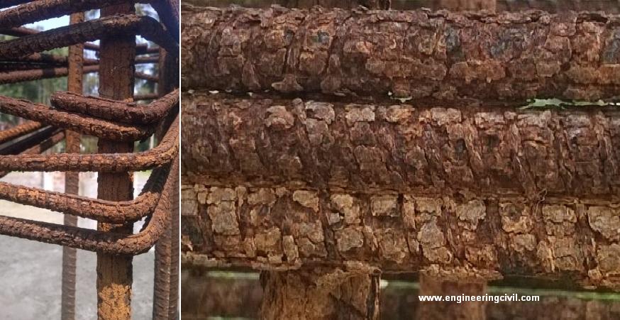
Investigation : The foundation was completed 3 months back and the dowels were exposed to atmosphere unguarded for 3 months in the rainy season.
Precaution to be taken : If a rebar or dowel is kept exposed, it should be covered with cement sand slurry and the coating needs to be applied every fortnight.
3.0 Case2: G+1 Building in Auraiya, UP
Observation month : November, 2015
Site condition : Good quality soil, No engineer consulted
Observation : Poor workmanship (Improper transfer of load due to poor centering)
Investigation : The centering was done by a normal mason and proper techniques were not used. Also due to congestion of rebars at beam column junction the mason avoids compaction which leads to honeycombing.
Precaution to be taken : Centering has to be done by training centering masons and site supervision by engineers is necessary during foundation centering, casting and casting at every slab. Compaction needs to be done homogenously at every stage of construction.

The upper concrete column is not aligned with the lower brick pedestal. This leads to unequal load transfer and added stress at the junction.

Honeycombing due to improper compaction

Reinforcement continuation at beam-column junction
4.0 Case3: G+2 Building in Abohar, Punjab
Observation month : August, 2015
Site condition : Good quality soil, designby engineer ignored during construction
Observation : Poor concrete mix and water quality
Investigation : The water quality was not checked before use. After testing it was found that the concrete did not achieve the desired strength of 20 MPa due to poor quality of concrete mix and water.
Precaution to be taken : The quality of all building material (cement, stonechips, sand and water) needs to be checked before mixing. Also the pH of water should be more than 6, i.e. not acidic. Any deviation from design should be approved by the structural engineer.

5.0 Case4: G+5 Building in Dhanu, Maharashtra
Observation month : August, 2015
Site condition : Good quality soil, 1 km from sea coast
Observation : Deep cracks in ground floor columns and concrete chipping all over the building
Investigation : Beach sand (high salinity) was used for construction. Also ground water (without chemical testing done) was used in concrete.
Precaution to be taken : The quality of building materials should follow the quality norm as mentioned in IS 456: 2008 Section 2. The detail is given in the chart.
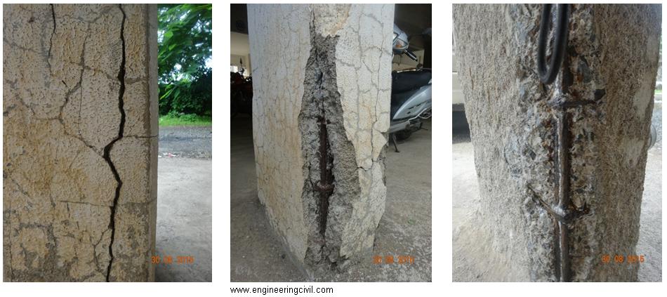
Deep cracks formed. Rebar gets exposed.
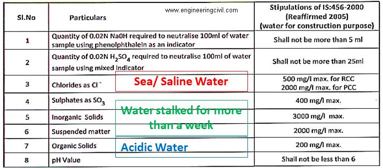
6.0 Case5: G+9 Building in Ahmedabad, Gujarat
Observation month : August, 2015
Site condition : Good quality soil, Good construction quality, no soil testing done
Observation : Column bars bent due to sudden thunder storm and landslide
Investigation : The soil was not tested before construction. Hence when sudden thunderstorm came and flooding at site occurred, the soil of straight cut walls failed and the landslide occur.
Precaution to be taken : Soil has to be tested for both chemical properties and strength before design and construction starts. The side wall of excavated site should have a slope of more than 30 degrees. In case of weak soil, micro pile or wooden sheet pile needs to be used to arrest soil.

Thankful to Er Priyanka Gupta
======================================================
Design Aspects For Terrorist Resistant Buildings
ABSTRACT:
All western democracies are now acutely aware of the apocalyptic consequences of a well-orchestrated attack on high-profile government facilities and other related targets. Many of these buildings are historical, ornate, listed and constructed using traditional techniques. Many of the modern retrofitted reinforcement techniques used to protect these structures against terrorist attacks are unsightly, intrusive or inappropriate. However, security specialists are well aware that while there might be little that can be done to defend a building against an aircraft attack, much can be done to defeat the more traditional car bomb and bullet. The methods available to the structural engineer to strengthen existing structures and provide resistance to the effects of a blast attacks are discussed in this paper.
1. INTRODUCTION:
The design of civilian or commercial buildings to withstand the effects of a terrorist blast is unlike the design of military installations or the design of embassy buildings. The objectives of the “Structural Engineering Guidelines” for the Design of New Embassy Buildings are to prevent heavy damage to components and structural collapse. Adherence to the provisions of the guidelines will minimize injuries and loss of life and facilitate the evacuation and rescue of survivors. The blast-protection objective of any commercial or public building must be similar to those of embassy structures, that is, to prevent structural collapse, to save lives, and to evacuate victims.
Architectural and structural features play a significant role in determining how the building will respond to the blast loading. These features can include adjacent or underground parking, atriums, transfer girders, slab configurations, and structural-frame systems. The keep-out distance is vital in the design of blast resistant structures since it is the key parameter that determines the blast overpressures that load the building and its structural elements. The degree of fenestration is another key parameter as it determines the pressures that enter the structure. The smaller the door and window openings the Embassies and military structures occupy secure sites with substantial keep-out distances better protected the occupants are within the structure. Following these key parameters,
2. EXPLOSION-MAJOR OF ALL THE TERRORIST ACTIVITIES
The probability that any single building will sustain damage from accidental or deliberate explosion is very low, but the cost for those who are unprepared is very high.
2.1 EXPECTED TERRORIST BLASTS ON STRUCTURES.
• External car bomb
• Internal car bomb
• Internal package
• Suicidal car bombs
• External car bomb
• Internal car bomb
• Internal package
• Suicidal car bombs
2.2 MAJOR CAUSES OF LIFE LOSS AFTER THE BLAST.
• Flying debris
• Broken glass
• Smoke and fire
• Blocked glass
• Power loss
• Communications breakdown
• Progressive collapse of structure
• Flying debris
• Broken glass
• Smoke and fire
• Blocked glass
• Power loss
• Communications breakdown
• Progressive collapse of structure
3. GOALS OF BLAST RESISTANT DESIGN
The goals of blast-resistant design are to:
• Reduce the severity of injury
• Facilitate rescue
• Expedite repair
• Accelerate the speed of return to full operations.
• Reduce the severity of injury
• Facilitate rescue
• Expedite repair
• Accelerate the speed of return to full operations.
4. BASIC REQUIREMENTS TO RESIST BLAST LOADS
To resist blast loads,
– The first requirement is to determine the threat. The major threat is caused by terrorist bombings. The threat for a conventional bomb is defined by two equally important elements, the bomb size, or charge weight, and the standoff distance – the minimum guaranteed distance between the blast source and the target
– Another requirement is to keep the bomb as far away as possible, by maximizing the keepout distance. No matter what size the bomb, the damage will be less severe the further the target is from the source.
– Structural hardening should actually be the last resort in protecting a structure; detection and prevention must remain the first line of defense. As terrorist attacks range from the small letter bomb to the gigantic truck bomb as experienced in Oklahoma City, the mechanics of a conventional explosion and their effects on a target must be addressed.
4.1. MECHANICS OF A CONVENTIONAL EXPLOSION
With the detonation of a mass of TNT at or near the ground surface, the peak blast pressures resulting from this hemispherical explosion decay as a function of the distance from the source as the ever-expanding shock front dissipates with range. The incident peak pressures are amplified by a reflection factor as the shock wave encounters an object or structure in its path. Except for specific focusing of high intensity shock waves at near 45° incidence, these reflection factors are typically greatest for normal incidence (a surface adjacent and perpendicular to the source) and diminish with the angle of obliquity or angular position relative to the source. Reflection factors depend on the intensity of the shock wave, and for large explosives at normal incidence these reflection factors may enhance the incident pressures by as much as an order of magnitude Charges situated extremely close to a target structure impose a highly impulsive, high intensity pressure load over a localized region of the structure; charges situated further away produce a lower-intensity, longer-duration uniform pressure distribution over the entire structure. In short by purely geometrical relations, the larger the standoff, the more uniform the pressure distribution over the target. Eventually, the entire structure is engulfed in the shock wave, with reflection and diffraction effects creating focusing and shadow zones in a complex pattern around the structure. Following the initial blast wave, the structure is subjected to a negative pressure, suction phase and eventually to the quasi-static blast wind. During this phase, the weakened structure may be subjected to impact by debris that may cause additional damage
With the detonation of a mass of TNT at or near the ground surface, the peak blast pressures resulting from this hemispherical explosion decay as a function of the distance from the source as the ever-expanding shock front dissipates with range. The incident peak pressures are amplified by a reflection factor as the shock wave encounters an object or structure in its path. Except for specific focusing of high intensity shock waves at near 45° incidence, these reflection factors are typically greatest for normal incidence (a surface adjacent and perpendicular to the source) and diminish with the angle of obliquity or angular position relative to the source. Reflection factors depend on the intensity of the shock wave, and for large explosives at normal incidence these reflection factors may enhance the incident pressures by as much as an order of magnitude Charges situated extremely close to a target structure impose a highly impulsive, high intensity pressure load over a localized region of the structure; charges situated further away produce a lower-intensity, longer-duration uniform pressure distribution over the entire structure. In short by purely geometrical relations, the larger the standoff, the more uniform the pressure distribution over the target. Eventually, the entire structure is engulfed in the shock wave, with reflection and diffraction effects creating focusing and shadow zones in a complex pattern around the structure. Following the initial blast wave, the structure is subjected to a negative pressure, suction phase and eventually to the quasi-static blast wind. During this phase, the weakened structure may be subjected to impact by debris that may cause additional damage
5. TREATMENTS PROVIDED TO VARIOUS PARTS OF A STRUCTURE TO IMPROVE BLAST RESISTING MECHANISM
5.1 FLOOR SLABS
Treatments for conventional flat slab design are as follows:
1. More attention must be paid to the design and detailing of exterior bays and lower floors, which are the most susceptible to blast loads.
2. In exterior bays/lower floors, drop panels and column capitols are required to shorten the effective slab length and improve the punching shear resistance.
3. If vertical clearance is a problem, shear heads embedded in the slab will improve the shear resistance and improve the ability of the slab to transfer moments to the columns.
4. The slab-column interface should contain closed-hoop stirrup reinforcement properly anchored around flexural bars within a prescribed distance from the column face.
5. Bottom reinforcement must be provided continuous through the column. This reinforcement serves to prevent brittle failure at the connection and provides an alternate mechanism for developing shear transfer once the concrete has punched through.
6. The development of membrane action in the slab, once the concrete has failed at the column interface, provides a safety net for the post damaged structure. Continuously tied reinforcement, spanning both directions, must be detailed properly to ensure that the tensile forces can be developed at the lapped splices. Anchorage of the reinforcement at the edge of the slab is required to guarantee the development of the tensile forces.
5.2 COLUMNS
Treatment for conventionally designed columns to improve blast resisting mechanism:
1. The potential for direct lateral loading on the face of the columns, resulting from the blast pressure and impact of explosive debris, requires that the lower-floor columns be designed with adequate ductility and strength
2. The perimeter columns supporting the lower floors must also be designed to resist this extreme blast effect
3. Encasing these lower-floor columns in a steel jacket will provide confinement, increase shear capacity, and improve the columns’ ductility and strength. An alternative, which provides similar benefits, is to embed a steel column within the perimeter concrete columns or wall section.
4. The possibility of uplift must be considered, and, if deemed likely, the columns must be reinforced to withstand a transient tensile force.
5. For smaller charge weights, spiral reinforcement provides a measure of core confinement that greatly improves the capacity and the behavior of the reinforced concrete columns under extreme load.
5.3 TRANSFER GIRDERS
The building relies on transfer girders at the top of the atrium to distribute the loads of the columns above the atrium to the adjacent columns outside the atrium. The transfer girder spans the width of the atrium, which insures a column-free architectural space for the entrance to the building.
The building relies on transfer girders at the top of the atrium to distribute the loads of the columns above the atrium to the adjacent columns outside the atrium. The transfer girder spans the width of the atrium, which insures a column-free architectural space for the entrance to the building.
Transfer girders typically concentrate the load-bearing system into a smaller number of structural elements. This load-transfer system runs contrary to the concept of redundancy desired in a blast environment. The column connections, which support the transfer girders, are to provide sustained strength despite inelastic deformations. The following recommendations must be met for transfer girders:
1. The transfer girder and the column connections must be properly designed and detailed, using an adequate blast loading description.
2. A progressive-collapse analysis must be performed, particularly if the blast loading exceeds the capacity of the girder
5.4 GLAZING
Typical annealed plate glass is only capable of resisting, at most, 14 kPa of blast pressure and it behaves poorly on explosion. On failure annealed glass creates large sharp edged shards, resembling knives and daggers which cause injuries and casualties..
Typical annealed plate glass is only capable of resisting, at most, 14 kPa of blast pressure and it behaves poorly on explosion. On failure annealed glass creates large sharp edged shards, resembling knives and daggers which cause injuries and casualties..
There exist better types of glazing that can resist some modest blast pressures. Thermally Tempered Glass (TTG) and Polycarbonate layups can be made in sheets up to about l-in. thick and can resist pressures up to about 200 to 275KPa. The greatest benefit of TTG is unlike annealed glass; TTG breaks into rock-salt sized pieces that will inflict less injury on the occupants. The failed Polycarbonate glass unfortunately remains in one piece,
5.5 EXTERNAL TREATMENTS
The two parameters that most directly influence the blast environment that the structure will be subjected to are the bomb’s charge weight and the standoff distance. Of these two, the only parameter that anyone has any control over is the standoff distance.
The two parameters that most directly influence the blast environment that the structure will be subjected to are the bomb’s charge weight and the standoff distance. Of these two, the only parameter that anyone has any control over is the standoff distance.
5.6 FACADE AND ATRIUM
The facade is comprised of the glazing and the exterior wall. Better glazing has already been discussed above and wall obviously should be hardened to resist the loading
The facade is comprised of the glazing and the exterior wall. Better glazing has already been discussed above and wall obviously should be hardened to resist the loading
Presence of an atrium along the face of the structure will require two protective measures. On the outside of the structure, the glass and glass framing must be strengthened to withstand the loads. On the inside, the balcony parapets, spandrel beams, and exposed slabs must be strengthened to withstand the loads that enter through the shattered glass.
5.7 OVERALL LATERAL BUILDING RESISTANCE, SHEAR WALLS
The ability of structures to resist a highly impulsive blast loading depends on the ductility of the load-resisting system. This means that the structure has to be able to deform in elastically under extreme overload, thereby dissipating large amounts of energy, prior to failure..In addition to providing ductile behavior for the structure, the following provisions would improve the blast protection capability of the building:
The ability of structures to resist a highly impulsive blast loading depends on the ductility of the load-resisting system. This means that the structure has to be able to deform in elastically under extreme overload, thereby dissipating large amounts of energy, prior to failure..In addition to providing ductile behavior for the structure, the following provisions would improve the blast protection capability of the building:
1. Use a well-distributed lateral-load resisting mechanism in the horizontal floor plan. This can be accomplished by using several shear walls around the plan of the building this will improve the overall seismic as well as the blast behavior of the building.
2. If adding more shear walls is not architecturally feasible, a combined lateral-load resisting mechanism can also be used. A central shear wall and a perimeter moment-resisting frame will provide for a balanced solution. The perimeter moment-resisting frame will require strengthening the spandrel beams and the connections to the outside columns. This will also result in better protection of the outside columns.
Several recommendations were presented for each of the identified features. The implementation of these recommendations will greatly improve the blast-resisting capability of the building under consideration.
5.8 LOWER FLOOR EXTERIOR
The architectural design of the building of interest currently calls for window glass around the first floor. Unless this area is constructed in reinforced concrete, the damage to the lower floor structural elements and their connections will be quite severe. Consequently, the injury to the lower floor inhabitants will be equally severe. In general, two sizes of charges can be discussed
The architectural design of the building of interest currently calls for window glass around the first floor. Unless this area is constructed in reinforced concrete, the damage to the lower floor structural elements and their connections will be quite severe. Consequently, the injury to the lower floor inhabitants will be equally severe. In general, two sizes of charges can be discussed
1. To protect against a small charge weight, a nominal 300 mm (12 in.) thick wall with 0.3% steel doubly reinforced in both directions might be required.
2. For intermediate charge weight protection, a 460 mm (18 in.) thick wall with 0.5% steel might be needed.
5.9 Stand Off DISTANCE
The keep out distance, within which explosives-laden vehicles may not penetrate, must be maximized and guaranteed. As we all know, the greater the standoff distance, the more the blast forces will dissipate resulting in reduced pressures on the building. Several recommendations can be made to maintain and improve the standoff distance for the building under consideration:
The keep out distance, within which explosives-laden vehicles may not penetrate, must be maximized and guaranteed. As we all know, the greater the standoff distance, the more the blast forces will dissipate resulting in reduced pressures on the building. Several recommendations can be made to maintain and improve the standoff distance for the building under consideration:
1. Use anti-ram bollards or large planters, placed around the entire perimeter. These barriers must be designed to resist the maximum vehicular impact load that could be imposed. For maximum effectiveness, the barriers-bollards or planters-must be placed at the curb.
2. The public parking lot at the corner of the building must be secured to guarantee the prescribed keepout distance from the face of the structure. Preferably, the parking lot should be eliminated.
3. Street parking should not be permitted on the near side of the street, adjacent to the building
4. An additional measure to reduce the chances of an attack would be to prevent parking on the opposite side of the street. While this does not improve the keep out distance, it could eliminate the “parked” bomb, thereby limiting bombings to “Park and run”
5.10 INTERNAL EXPLOSION THREATS
The blast environment could be introduced into the interior of the structure in four vulnerable locations:
The blast environment could be introduced into the interior of the structure in four vulnerable locations:
The entrance lobby, the basement mechanical rooms, the loading dock, and the primary mail rooms. Specific modifications to the features of these vulnerable spaces can prevent an internal explosion from causing extensive damage and injury inside the building.
1. Walls and slabs adjacent to the lobby, loading dock, and mail rooms must be hardened to protect against the hand delivered package bomb, nominally a 10-20 kg explosive. This hardening can be achieved by redesigning the slabs and erecting cast-in-place reinforced-concrete walls, with the thickness and reinforcement determined relative to the appropriate threats.
2. The basement must be similarly isolated from all adjacent occupied office space, including the floor above, from the threat of a small package bomb.
6. CASE STUDY – WORLD TRADE CENTER COLLAPSE.
The collapse of the World Trade Center (WTC) towers on September 11, 2001, was as sudden as it was dramatic; the complete destruction of such massive buildings shocked nearly everyone. Immediately afterward and even today, there is widespread speculation that the buildings were structurally deficient, that the steel columns melted, or that the fire suppression equipment failed to operate. In order to separate the fact from the fiction, I have attempted to quantify various details of the collapse.
The major events include the following:
The airplane impact with damage to the columns.
The ensuing fire with loss of steel strength and distortion (figure 6.3)
The collapse, which generally occurred inward without significant tipping. (figure6.4)
Before going to the details it is useful to review the overall design of the towers.
6.1 THE DESIGN
The towers were designed and built in the mid-1960s through the early 1970s each tower was 64 m square, standing 411 m above street level and 21 m below grade. This produces a height-to-width ratio of 6.8. The total weight of the structure was roughly 500,000 t. The building is a huge sail that must resist a 225 km/h hurricane. It was designed to resist a wind load of 2 KPa—a total of lateral load of 5,000 t.
The towers were designed and built in the mid-1960s through the early 1970s each tower was 64 m square, standing 411 m above street level and 21 m below grade. This produces a height-to-width ratio of 6.8. The total weight of the structure was roughly 500,000 t. The building is a huge sail that must resist a 225 km/h hurricane. It was designed to resist a wind load of 2 KPa—a total of lateral load of 5,000 t.
In order to make each tower capable of withstanding this wind load, the architects selected a lightweight “perimeter tube” design consisting of 244 exterior columns of 36 cm square steel box section on 100 cm centers(figure 3). This permitted windows more than one-half meter wide. Inside this outer tube there was a 27 m × 40 m core, which was designed to support

Figure 6.1 a cutaway view of WTC structure.
The weight of the tower It also housed the elevators, the stairwells, and the mechanical risers and utilities. Web joists 80 cm tall connected the core to the perimeter at each story. Concrete slabs were poured over these joists to form the floors. In essence, the building is an egg-crate construction, i.e. 95 percent air.
The egg-crate construction made a redundant structure (i.e., if one or two columns were lost, the loads would shift into adjacent columns and the building would remain standing). The WTC was primarily a lightweight steel structure; however, its 244 perimeter columns made it “one of the most redundant and one of the most resilient” skyscrapers.
6.2 DETAILS OF THE COLLAPSE
6.2.1 THE AIRPLANE IMPACT
6.2.1 THE AIRPLANE IMPACT
The early news reports noted how well the towers withstood the initial impact of the aircraft; however, when one recognizes that the buildings had more than 1,000 times the mass of the aircraft and had been designed to resist steady wind loads of 30 times the weight of the aircraft, this ability to withstand the initial impact is hardly surprising. Furthermore, since there was no significant wind on September 11, the outer perimeter columns were only stressed before the impact to around 1/3 of their 200 MPa design allowable.

Figure 6.2 A graphic illustration, from the USA Today newspaper web site, of the World Trade Center points of impact.
The only individual metal component of the aircraft that is comparable in strength to the box perimeter columns of the WTC is the keel beam at the bottom of the aircraft fuselage. While the aircraft impact undoubtedly destroyed several columns in the WTC perimeter wall, the number of columns lost on the initial impact was not large and the loads were shifted to remaining columns in this highly redundant structure. Of equal or even greater significance during this initial impact was the explosion when 90,000 L gallons of jet fuel, comprising nearly 1/3 of the aircraft’s weight, ignited. The ensuing fire was clearly the principal cause of the collapse (see figure 6.2)

Figure 6.3 Flames and debris exploded from the World Trade Center south tower immediately after the airplane’s impact. The black smoke indicates a fuel-rich fire
The fire is the most misunderstood part of the WTC collapse. Even today, the media report (and many scientists believe) that the steel melted. It is argued that the jet fuel burns very hot, especially with so much fuel present. This is not true.
Part of the problem is that people often confuse temperature and heat. While they are related, they are not the same. Thermodynamically, the heat contained in a material is related to the temperature through the heat capacity and the mass. Temperature is defined as an intensive property, meaning that it does not vary with the quantity of material, while the heat is an extensive property, which does vary with the amount of material. One way to distinguish the two is to note that if a second log is added to the fireplace, the temperature does not double; it stays roughly the same, but the length of time the fire burns, doubles and the heat so produced is doubled. Thus, the fact that there were 90,000 L of jet fuel on a few floors of the WTC does not mean that this was an unusually hot fire. The temperature of the fire at the WTC was not unusual, and it was most definitely not capable of melting steel.
In combustion science, there are three basic types of flames, namely, a jet burner, a pre-mixed flame, and a diffuse flame. A jet burner generally involves mixing the fuel and the oxidant in nearly stoichiometric proportions and igniting the mixture in a constant-volume chamber. Since the combustion products cannot expand in the constant-volume chamber, they exit the chamber as a very high velocity, fully combusted, jet. This is what occurs in a jet engine, and this is the flame type that generates the most intense heat.
In a pre-mixed flame, the same nearly stoichiometric mixture is ignited as it exits a nozzle, under constant pressure conditions. It does not attain the flame velocities of a jet burner. An oxyacetylene torch or a Bunsen burner is a pre-mixed flame.
In a diffuse flame, the fuel and the oxidant are not mixed before ignition, but flow together in an uncontrolled manner and combust when the fuel/oxidant ratios reach values within the flammable range. A fireplace flame is a diffuse flame burning in air, as was the WTC fire. Diffuse flames generate the lowest heat intensities of the three flame types.
If the fuel and the oxidant start at ambient temperature, a maximum flame temperature can be defined. For carbon burning in pure oxygen, the maximum is 3,200°C; for hydrogen it is 2,750°C. Thus, for virtually any hydrocarbons, the maximum flame temperature, starting at ambient temperature and using pure oxygen, is approximately 3,000°C.
This maximum flame temperature is reduced by two-thirds if air is used rather than pure oxygen. The reason is that every molecule of oxygen releases the heat of formation of a molecule of carbon monoxide and a molecule of water. If pure oxygen is used, this heat only needs
To heat two molecules (carbon monoxide and water), while with air, these two molecules must be heated plus four molecules of nitrogen. Thus, burning hydrocarbons in air produces only one-third the temperature increase as burning in pure oxygen because three times as many molecules must be heated when air is used. The maximum flame temperature increase for burning hydrocarbons (jet fuel) in air is, thus, about 1,000°C—hardly sufficient to melt steel at 1,500°C.
6.2.3 THE COLLAPSE

Figure 6.4 as the heat of the fire intensified, the joints on the most severely burned floors gave way, causing the perimeter wall columns to bow outward and the floors above them to fall. The buildings collapsed within ten seconds, hitting bottom with an estimated speed of 200 km/hr.
Nearly every large building has a redundant design that allows for loss of one primary structural member, such as a column. However, when multiple members fail, the shifting loads eventually overstress the adjacent members and the collapse occurs like a row of dominoes falling down.
The perimeter tube design of the WTC was highly redundant. It survived the loss of several exterior columns due to aircraft impact, but the ensuing fire led to other steel failures. Many structural engineers believe that the weak points—were the angle clips that held the floor joists between the columns on the perimeter wall and the core structure .With a 700 Pa floor design allowable, each floor should have been able to support approximately 1,300 t beyond its own weight. The total weight of each tower was about 500,000 t.
As the joists on one or two of the most heavily burned floors gave way and the outer box columns began to bow outward, the floors above them also fell. The floor below (with its 1,300 t design capacity) could not support the roughly 45,000 t of ten floors (or more) above crashing down on these angle clips. This started the domino effect that caused the buildings to collapse within ten seconds, hitting bottom with an estimated speed of 200 km per hour. If it had been free fall, with no restraint, the collapse would have only taken eight seconds and would have impacted at 300 km/h.
Can buildings resist direct airplane hits?
If the “design” terrorist attack is similar to that of Sept. 11, can buildings be given the capacity to meet this demand? To answer this question, it is important to understand the physics at work when a plane in flight is stopped by a building.
If the “design” terrorist attack is similar to that of Sept. 11, can buildings be given the capacity to meet this demand? To answer this question, it is important to understand the physics at work when a plane in flight is stopped by a building.
If the performance objective is to “resist” a direct airplane hit and protect people inside the building, the plane cannot be allowed to penetrate the exterior wall. To stop a Boeing 767 traveling in excess of 500 miles per hour in a distance of a few feet would take a deceleration force in excess of 400 million pounds.
Each tower of the World Trade Center was designed for a total horizontal force (or “design wind load”) of about 15 million pounds. The total design wind load for a more commonly sized high-rise, say, 40 stories tall, would be about 4 million pounds. In other words, to resist the amount of force generated by a direct 767 hit, today’s buildings would need to be 100 times stronger than dictated by code, which is both physically and economically impossible.
So why did the World Trade Center Towers not collapse immediately due to the impact load on the system? The planes did not stop in a few feet, but had an effective stopping distance of over 100 feet. This would drop the deceleration force down to something close to the capacity of the building.
Another part of the answer to this question lies in the way that the exterior of the building was structured. The exterior columns were 14-inch square welded steel box columns spaced at 40 inches on center. This means that there was only 26 inches clear between each column. The columns were integral with the steel spandrels beams and formed essentially a solid wall of steel with perforations for windows. This wall construction was able to form a Vierendeel “bridge” over the hole created in one side of each of the towers.
Both of these facts — that the plane was not stopped at the exterior and that the columns and spandrels were extremely dense — were necessary to prevent the building from collapsing immediately upon impact.
Can buildings be designed for direct airplane hits? Yes and no. Yes, for small aircraft. A definite no, for large commercial aircraft.
How can we minimize the chance of progressive collapse?
This is still one more question that some people are asking. Because the towers ultimately collapsed with one floor crashing down upon the next, it has been called a progressive collapse.
This is still one more question that some people are asking. Because the towers ultimately collapsed with one floor crashing down upon the next, it has been called a progressive collapse.
Again, it is important to think carefully about the question. Aren’t all collapses progressive? Something breaks, and then something else breaks, and so on. Normally, when the term progressive collapse is used, it specifically refers to the loss of one or two columns or bearing walls that cause a collapse to propagate vertically.
In the case of the World Trade Center there were about 40 columns lost on one face of each of the towers and there was no propagation of collapse from this loss. So did the World Trade Center have good resistance to progressive collapse? By normal use of the term “progressive collapse” it did. The collapse that did ultimately occur was progressive, like all collapses, but was not “progressive collapse” that some international codes address.
The difficulty in understanding this concept is illustrated with the following story.
A New York fire chief wrote that experienced firefighters know that the buildings that are most susceptible to progressive collapse are buildings that are well-tied together (i.e., able to transfer building loads from one element to another, such as a column). Yet, virtually every structural engineer will advise that one of the best ways to prevent progressive collapse is to tie the building together. How can there be this kind of a contradiction?
The difference is that the engineer is thinking about losing a column or two and the fire chief is talking about losing a whole part of a building. As the event that initiates the progressive collapse becomes larger than losing a column, the risk becomes that the strong horizontal ties of a building will cause the collapse to propagate horizontally.
Any discussion of code provisions with respect to progressive collapse must recognize that both the engineer and the fire chief are right depending on the kind of hazard that is defined.
At least six safety systems present in the World Trade Center towers were completely and immediately disabled or destroyed upon impact: fireproofing, automatic sprinklers, compartmentalization and pressurization, lighting, structure and exit stairs.
Conclusions
There are structural techniques that can increase the capacity of building structures to resist certain kinds of terrorist attacks. However, there is absolutely no reliable way to design for the impact of a large scale commercial airliner.
There are structural techniques that can increase the capacity of building structures to resist certain kinds of terrorist attacks. However, there is absolutely no reliable way to design for the impact of a large scale commercial airliner.
REFERENCES
1. M.J Forrestal, and D.Y. Tzou, “A Spherical Cavity- Expansion Penetration Model for Concrete Targets”, International Journal of Solids and Structures, vol. 34, (31-32), (1997) 4127-4146.
2. M.J. Fo r restal, B.S. Altman, J.D. Cargile, and S.J. Hanchak, “An Empirical Equation for Penetration Depth of Ogive-Nose Projectiles into Concrete Targets,” InternationalJournal of Impact Engineering, vol. 15, (4) (1994), 395-405
3. D.J. Frew, J.D. Cargile, and J.Q. Ehrgott, “WES Geodynamics and Projectile Penetration Research Facilities”,in: Proceedings, Ad vances in Numerical simulation Techniquesfor Penetration and Perforation of Solids, E.P. Chen, and V. K . Luk, eds. American Society of Mechanical Engineers, New Orleans, LA, ASME Winter Annual Meeting, 28 Nov.-3 Dec. 1993, pp 1-8
4. E.F. O’Neil, and W.M. Dowd, “Reactive Powder Concrete: A New Material for the Construction Industry,” in: Proceedings,Third National Concrete and Masonry Engineering Conference S.K. Ghosh, ed., National Concrete and Masonry Engineering Conference, San Francisco, CA. June 15-17 1995, pp 43-50
5. www.berkley.edu
6. www.sciam.com
7. www.civil.usyd.edu
8. Civil engineering journal (oct. 1995)
9. Fire engineering journal (nov. 1995)
10. Structural design and construction journal (nov. 1996)
11. www.structuremag.org
12. Biggs, John M., Introduction to structural Dynamics, McGraw-hill, 1964.
=====================================================
Love your site. My thanks for doing such a good job. I will come back to read more and inform my coworkers about your site.
ReplyDeleteVisit Here : Structural Engineers in Coimbatore